How to Use VOLTAMMETR: Examples, Pinouts, and Specs
Introduction
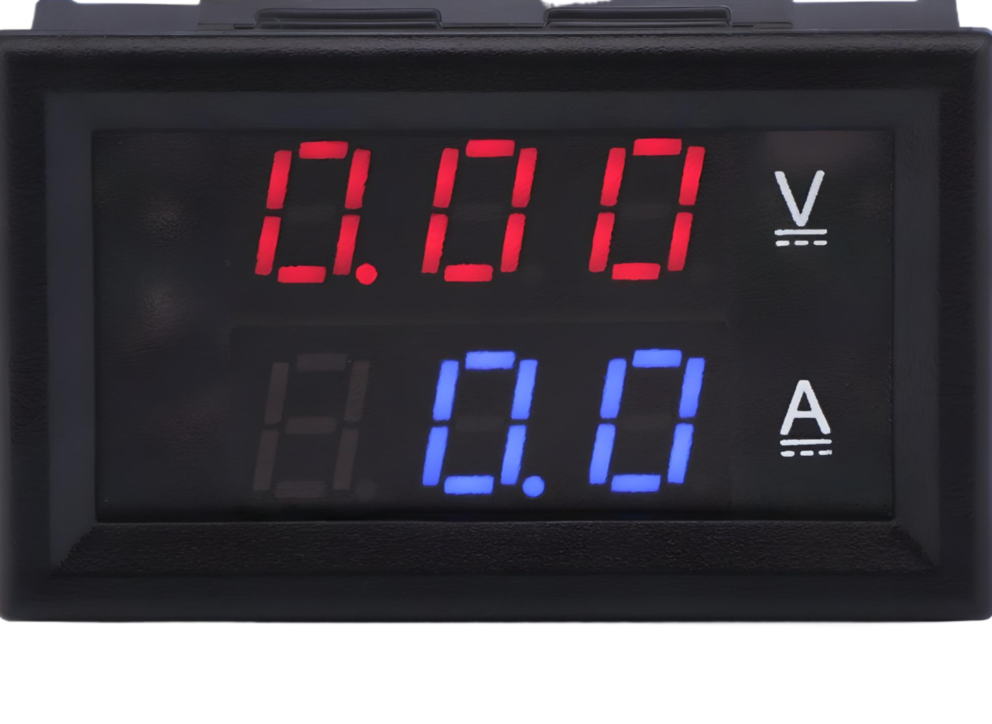
The VOLTAMMETR, manufactured by METR (Part ID: VOLT AMPER METR), is an electrochemical device designed to measure the quantity of electricity passing through a solution. It operates by analyzing the amount of gas produced or the change in mass of an electrode during electrolysis. This component is widely used in electrochemical experiments, battery testing, and educational demonstrations to study Faraday's laws of electrolysis.
Explore Projects Built with VOLTAMMETR
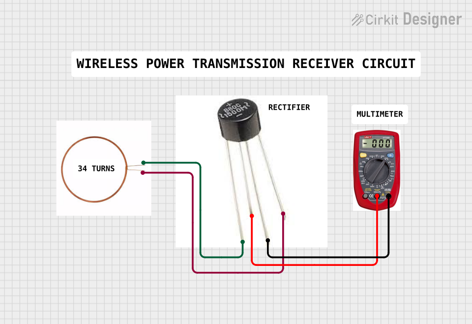
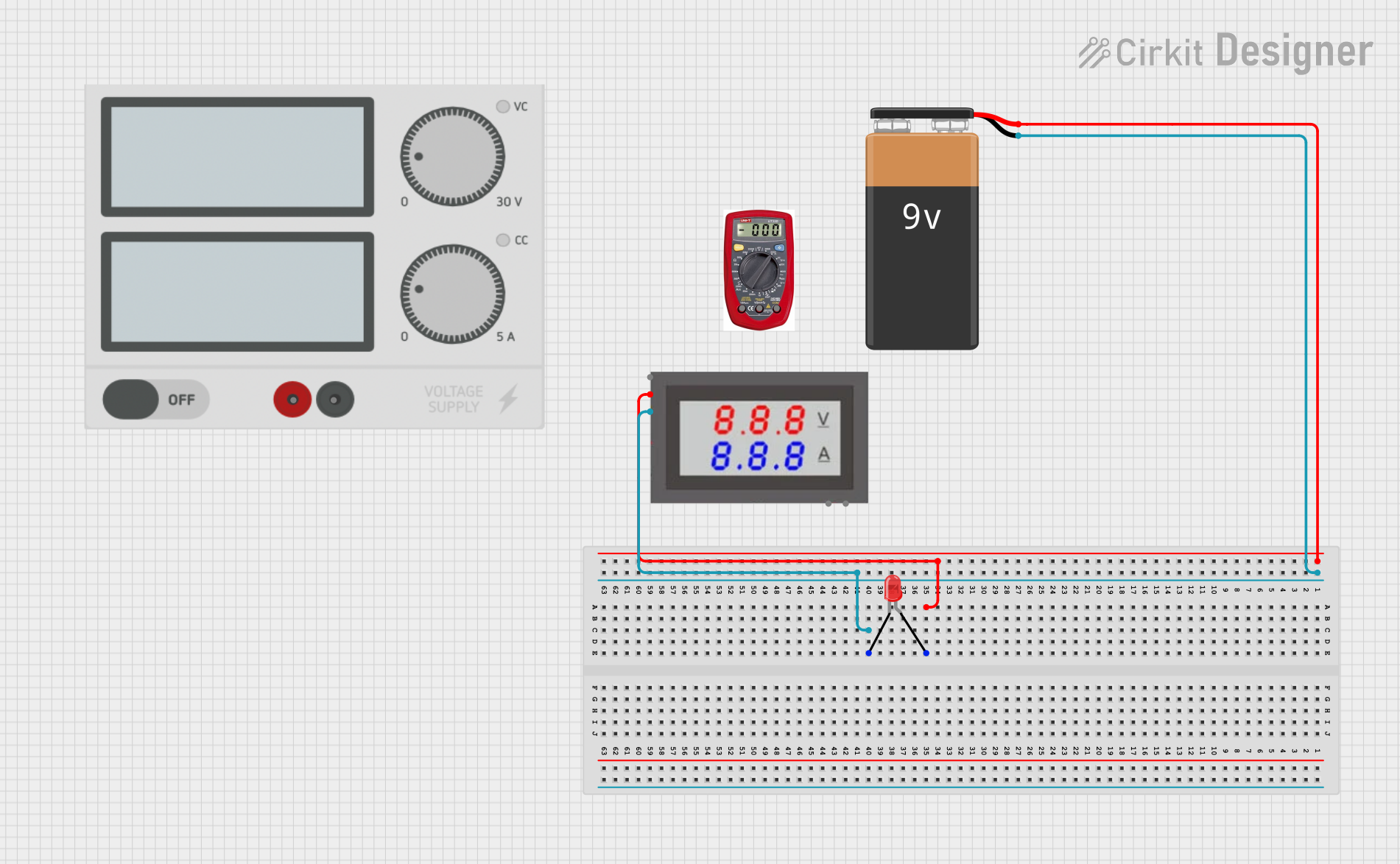
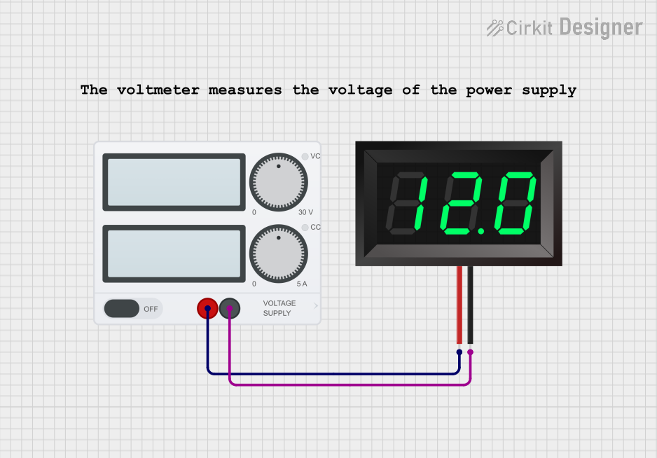
Explore Projects Built with VOLTAMMETR
Common Applications and Use Cases
- Electrochemical research and experiments
- Battery charge and discharge analysis
- Educational demonstrations of electrolysis principles
- Industrial electroplating and material testing
- Monitoring and quantifying electrochemical reactions
Technical Specifications
The VOLTAMMETR is a precision instrument designed for laboratory and industrial use. Below are its key technical details:
General Specifications
| Parameter | Value |
|---|---|
| Manufacturer | METR |
| Part ID | VOLT AMPER METR |
| Measurement Range | 0 – 10 Amperes, 0 – 100 Volts |
| Accuracy | ±0.5% |
| Operating Voltage | 5V DC (for internal circuitry) |
| Display Type | Digital (LCD) |
| Dimensions | 120mm x 80mm x 50mm |
| Weight | 250g |
Pin Configuration and Descriptions
The VOLTAMMETR has a simple pin interface for easy integration into circuits. Below is the pin configuration:
| Pin Number | Pin Name | Description |
|---|---|---|
| 1 | V+ | Positive voltage input for measurement |
| 2 | V- | Negative voltage input (ground) |
| 3 | A+ | Positive current input for measurement |
| 4 | A- | Negative current input (ground) |
| 5 | GND | Ground connection for internal circuitry |
| 6 | VCC | Power supply input (5V DC) for internal circuitry |
Usage Instructions
The VOLTAMMETR is straightforward to use in a variety of applications. Follow the steps below to integrate and operate the device:
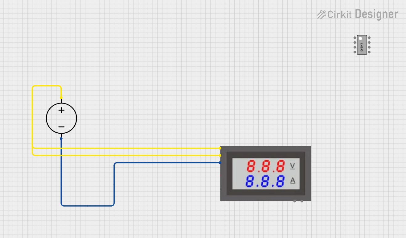
Connecting the VOLTAMMETR
- Power Supply: Connect the
VCCpin to a 5V DC power source and theGNDpin to the ground of the power source. - Voltage Measurement:
- Connect the
V+pin to the positive terminal of the voltage source to be measured. - Connect the
V-pin to the negative terminal (ground) of the voltage source.
- Connect the
- Current Measurement:
- Connect the
A+pin in series with the positive terminal of the load. - Connect the
A-pin to the load's positive terminal.
- Connect the
- Ensure all connections are secure and double-check polarity to avoid damage.
Important Considerations and Best Practices
- Polarity: Always ensure correct polarity when connecting the voltage and current inputs.
- Overload Protection: Do not exceed the specified measurement range (10A or 100V) to prevent damage.
- Calibration: Periodically calibrate the device for accurate measurements.
- Environmental Conditions: Operate the device within the recommended temperature range (0°C to 50°C) and avoid exposure to moisture.
Example: Using VOLTAMMETR with Arduino UNO
The VOLTAMMETR can be used with an Arduino UNO to log voltage and current measurements. Below is an example code snippet:
// Example code to read voltage and current from VOLTAMMETR using Arduino UNO
// Ensure proper connections: V+ and V- for voltage, A+ and A- for current

const int voltagePin = A0; // Analog pin for voltage measurement
const int currentPin = A1; // Analog pin for current measurement

void setup() {
  Serial.begin(9600); // Initialize serial communication
  pinMode(voltagePin, INPUT); // Set voltage pin as input
  pinMode(currentPin, INPUT); // Set current pin as input
}

void loop() {
  // Read analog values from VOLTAMMETR
  int voltageRaw = analogRead(voltagePin);
  int currentRaw = analogRead(currentPin);

  // Convert raw values to actual voltage and current
  float voltage = (voltageRaw / 1023.0) * 5.0 * 20.0; // Scale factor for 100V range
  float current = (currentRaw / 1023.0) * 5.0 * 2.0;  // Scale factor for 10A range

  // Print the results to the Serial Monitor
  Serial.print("Voltage: ");
  Serial.print(voltage);
  Serial.println(" V");

  Serial.print("Current: ");
  Serial.print(current);
  Serial.println(" A");

  delay(1000); // Wait for 1 second before next reading
}
Troubleshooting and FAQs
Common Issues and Solutions
No Display or Readings:
- Ensure the
VCCandGNDpins are properly connected to a 5V DC power source. - Check for loose connections or damaged wires.
- Ensure the
Inaccurate Measurements:
- Verify that the device is calibrated correctly.
- Ensure the input voltage and current are within the specified range.
Device Overheating:
- Avoid exceeding the maximum voltage (100V) or current (10A) limits.
- Check for proper ventilation and avoid prolonged operation at maximum ratings.
Fluctuating Readings:
- Ensure stable connections and minimize electrical noise in the circuit.
- Use shielded cables for high-accuracy applications.
Frequently Asked Questions
Q1: Can the VOLTAMMETR measure both AC and DC?
A1: No, the VOLTAMMETR is designed for DC measurements only.
Q2: How often should the device be calibrated?
A2: Calibration is recommended every 6 months or before critical measurements.
Q3: Can the device be used in outdoor environments?
A3: The VOLTAMMETR is not weatherproof and should only be used in dry, indoor environments.
Q4: What happens if the input exceeds the maximum range?
A4: Exceeding the range may damage the device. Use external protection circuits if necessary.
By following this documentation, users can effectively integrate and operate the METR VOLTAMMETR in their projects.