Cirkit Designer Logo
Cirkit Designer
Your all-in-one circuit design IDE
Home / 
Component Documentation

How to Use AHT10: Examples, Pinouts, and Specs

Image of AHT10
Cirkit Designer LogoDesign with AHT10 in Cirkit Designer

Introduction

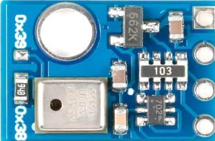
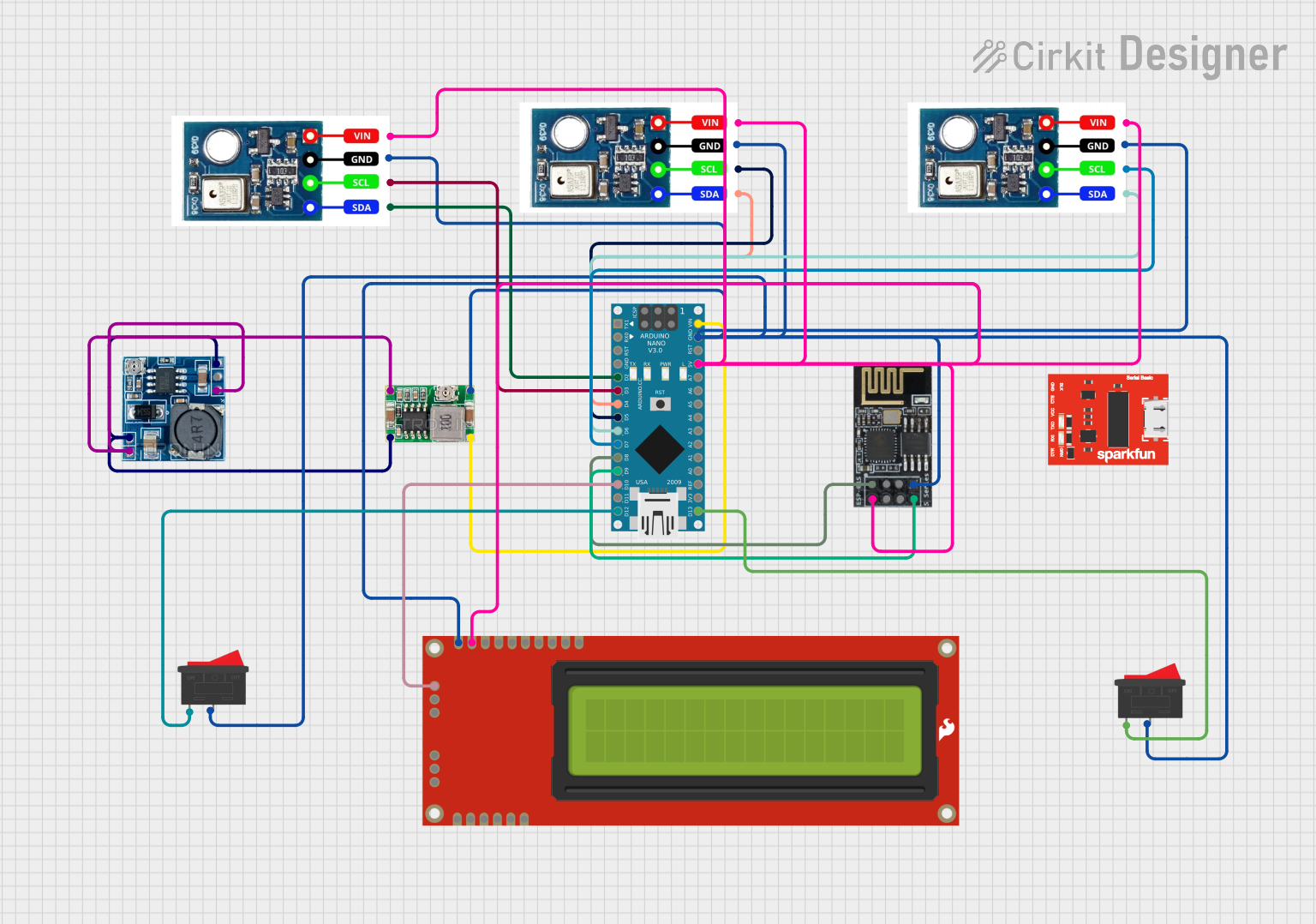
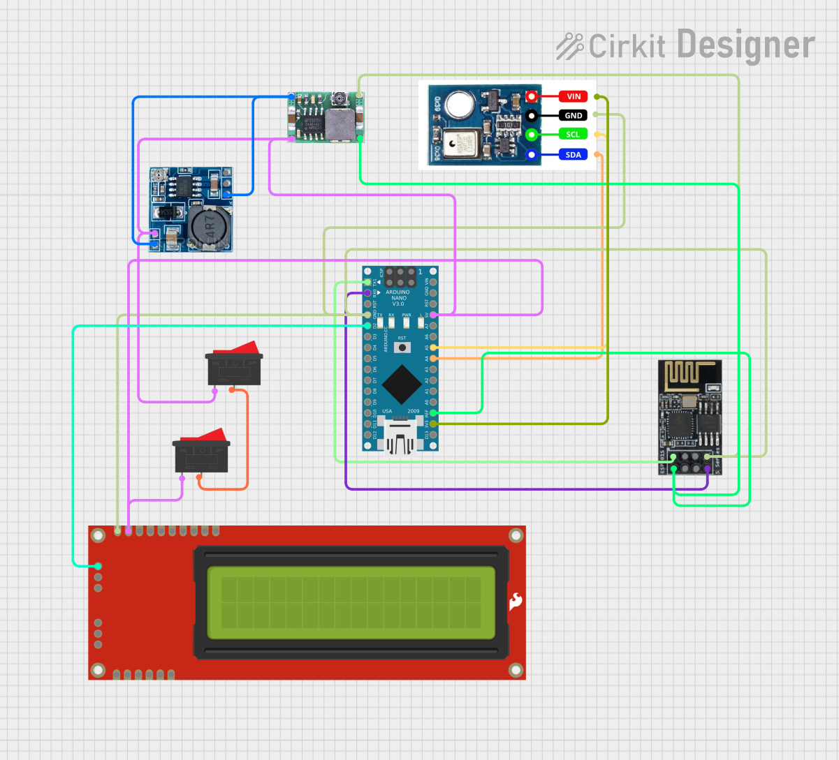
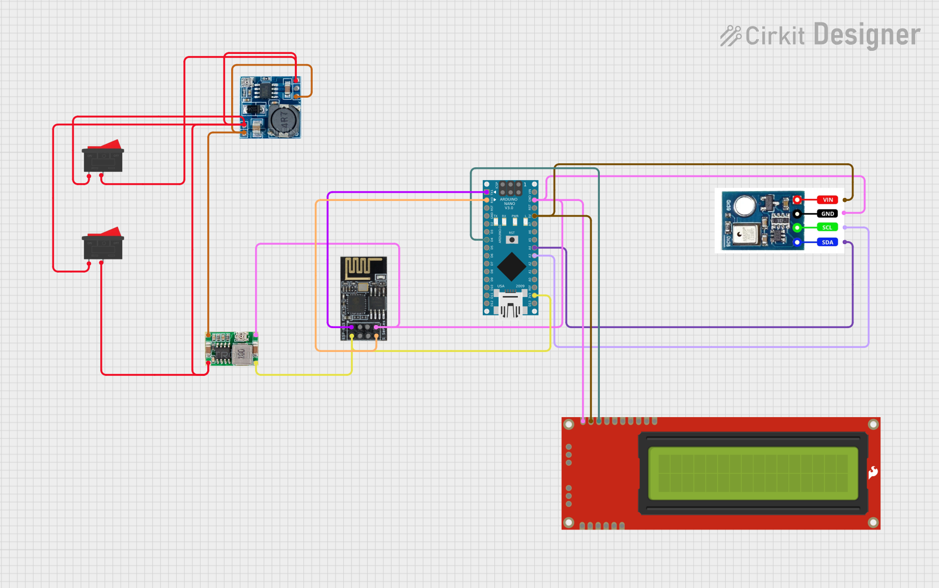
The AHT10 is a digital temperature and humidity sensor designed to provide accurate and reliable measurements of environmental conditions. It features a built-in I2C interface, making it easy to integrate with microcontrollers and other digital systems. The AHT10 is known for its high precision, low power consumption, and compact design, making it ideal for a wide range of applications.

Explore Projects Built with AHT10

Use Cirkit Designer to design, explore, and prototype these projects online. Some projects support real-time simulation. Click "Open Project" to start designing instantly!
Arduino Nano-Based Weather Station with Wi-Fi Connectivity and Multiple AHT10 Sensors
Image of PS2_Group 5: A project utilizing AHT10 in a practical application
This circuit features an Arduino Nano microcontroller interfacing with three AHT10 temperature and humidity sensors, an ESP8266-01 WiFi module, and a 16x2 LCD display. It includes power regulation components to step down voltage and manage power distribution, and rocker switches for user input. The setup is designed for environmental monitoring and data display with potential for wireless communication.
Cirkit Designer LogoOpen Project in Cirkit Designer
Arduino Nano and ESP8266 Wi-Fi Controlled Weather Station with LCD Display
Image of Grain Moisture Monitor: A project utilizing AHT10 in a practical application
This circuit is a microcontroller-based system that uses an Arduino Nano to read data from an AHT10 temperature and humidity sensor and display it on a 16x2 LCD. It also includes a WiFi module (ESP8266-01) for wireless communication, powered by a step-down module and a buck converter to provide the necessary voltage levels.
Cirkit Designer LogoOpen Project in Cirkit Designer
Wemos D1 Mini Based Soil Moisture and Temperature Monitoring System
Image of pfe2: A project utilizing AHT10 in a practical application
This circuit features a Wemos D1 Mini microcontroller connected to an AHT10 temperature and humidity sensor and a capacitive soil moisture sensor. The AHT10 communicates with the Wemos D1 Mini via I2C (with SDA connected to D2 and SCL to D1), while the soil moisture sensor's analog output is connected to the A0 pin of the Wemos D1 Mini. Both sensors and the microcontroller share a common power supply, with the 3V3 pin of the Wemos D1 Mini providing power to the sensors.
Cirkit Designer LogoOpen Project in Cirkit Designer
Arduino Nano Weather Station with AHT10 Sensor and Wi-Fi Connectivity
Image of Grain Moisture Monitoring: A project utilizing AHT10 in a practical application
This circuit uses an Arduino Nano to read temperature and humidity data from an AHT10 sensor, display the data on a Serial Enabled 16x2 LCD, and transmit it over WiFi using an ESP8266-01 module. Power is managed through a Step Down Module and a Mini 360 Buck Converter to provide the necessary voltages for the components.
Cirkit Designer LogoOpen Project in Cirkit Designer

Explore Projects Built with AHT10

Use Cirkit Designer to design, explore, and prototype these projects online. Some projects support real-time simulation. Click "Open Project" to start designing instantly!
Image of PS2_Group 5: A project utilizing AHT10 in a practical application
Arduino Nano-Based Weather Station with Wi-Fi Connectivity and Multiple AHT10 Sensors
This circuit features an Arduino Nano microcontroller interfacing with three AHT10 temperature and humidity sensors, an ESP8266-01 WiFi module, and a 16x2 LCD display. It includes power regulation components to step down voltage and manage power distribution, and rocker switches for user input. The setup is designed for environmental monitoring and data display with potential for wireless communication.
Cirkit Designer LogoOpen Project in Cirkit Designer
Image of Grain Moisture Monitor: A project utilizing AHT10 in a practical application
Arduino Nano and ESP8266 Wi-Fi Controlled Weather Station with LCD Display
This circuit is a microcontroller-based system that uses an Arduino Nano to read data from an AHT10 temperature and humidity sensor and display it on a 16x2 LCD. It also includes a WiFi module (ESP8266-01) for wireless communication, powered by a step-down module and a buck converter to provide the necessary voltage levels.
Cirkit Designer LogoOpen Project in Cirkit Designer
Image of pfe2: A project utilizing AHT10 in a practical application
Wemos D1 Mini Based Soil Moisture and Temperature Monitoring System
This circuit features a Wemos D1 Mini microcontroller connected to an AHT10 temperature and humidity sensor and a capacitive soil moisture sensor. The AHT10 communicates with the Wemos D1 Mini via I2C (with SDA connected to D2 and SCL to D1), while the soil moisture sensor's analog output is connected to the A0 pin of the Wemos D1 Mini. Both sensors and the microcontroller share a common power supply, with the 3V3 pin of the Wemos D1 Mini providing power to the sensors.
Cirkit Designer LogoOpen Project in Cirkit Designer
Image of Grain Moisture Monitoring: A project utilizing AHT10 in a practical application
Arduino Nano Weather Station with AHT10 Sensor and Wi-Fi Connectivity
This circuit uses an Arduino Nano to read temperature and humidity data from an AHT10 sensor, display the data on a Serial Enabled 16x2 LCD, and transmit it over WiFi using an ESP8266-01 module. Power is managed through a Step Down Module and a Mini 360 Buck Converter to provide the necessary voltages for the components.
Cirkit Designer LogoOpen Project in Cirkit Designer

Common Applications and Use Cases

  • Environmental monitoring systems
  • Smart home devices (e.g., thermostats, humidifiers)
  • Weather stations
  • Industrial automation
  • IoT (Internet of Things) devices
  • HVAC (Heating, Ventilation, and Air Conditioning) systems

Technical Specifications

  • Supply Voltage (VDD): 2.0V to 5.5V
  • Operating Current: 0.25 mA (average)
  • Standby Current: < 0.01 mA
  • Temperature Measurement Range: -40°C to 85°C
  • Temperature Accuracy: ±0.3°C
  • Humidity Measurement Range: 0% to 100% RH
  • Humidity Accuracy: ±2% RH
  • Communication Protocol: I2C
  • I2C Address: 0x38 (default)
  • Response Time: < 8 seconds
  • Dimensions: 4.0mm x 5.0mm x 1.6mm

Pin Configuration and Descriptions

The AHT10 sensor has four pins, as described in the table below:

Pin Number Pin Name Description
1 VDD Power supply (2.0V to 5.5V)
2 GND Ground
3 SCL I2C clock line
4 SDA I2C data line

Usage Instructions

How to Use the AHT10 in a Circuit

  1. Power Supply: Connect the VDD pin to a 3.3V or 5V power source and the GND pin to ground.
  2. I2C Communication: Connect the SCL and SDA pins to the corresponding I2C pins on your microcontroller. Use pull-up resistors (typically 4.7kΩ) on the SCL and SDA lines if they are not already present on your board.
  3. Initialization: Initialize the sensor in your microcontroller's code by sending the appropriate I2C commands to configure the AHT10.
  4. Data Reading: Use I2C commands to read temperature and humidity data from the sensor. The data is typically provided in a 6-byte format.

Important Considerations and Best Practices

  • Ensure the sensor is not exposed to direct sunlight or water, as this may affect its accuracy.
  • Avoid placing the sensor near heat sources or areas with high electromagnetic interference.
  • Use decoupling capacitors (e.g., 0.1µF) near the VDD pin to stabilize the power supply.
  • Allow the sensor to stabilize for a few seconds after power-up before taking measurements.

Example Code for Arduino UNO

Below is an example of how to use the AHT10 with an Arduino UNO:

#include <Wire.h> // Include the Wire library for I2C communication

#define AHT10_ADDRESS 0x38 // Default I2C address of the AHT10

void setup() {
  Wire.begin(); // Initialize I2C communication
  Serial.begin(9600); // Start serial communication for debugging

  // Initialize the AHT10 sensor
  Wire.beginTransmission(AHT10_ADDRESS);
  Wire.write(0xE1); // Send initialization command
  Wire.endTransmission();
  delay(10); // Wait for the sensor to initialize
}

void loop() {
  // Request data from the AHT10 sensor
  Wire.beginTransmission(AHT10_ADDRESS);
  Wire.write(0xAC); // Trigger measurement command
  Wire.write(0x33); // Command parameter
  Wire.write(0x00); // Command parameter
  Wire.endTransmission();
  delay(100); // Wait for the measurement to complete

  // Read 6 bytes of data from the sensor
  Wire.requestFrom(AHT10_ADDRESS, 6);
  if (Wire.available() == 6) {
    uint8_t data[6];
    for (int i = 0; i < 6; i++) {
      data[i] = Wire.read();
    }

    // Process the data to extract temperature and humidity
    uint32_t humidity = ((uint32_t)data[1] << 12) | ((uint32_t)data[2] << 4) |
                        (data[3] >> 4);
    uint32_t temperature = ((uint32_t)(data[3] & 0x0F) << 16) |
                           ((uint32_t)data[4] << 8) | data[5];

    float humidityPercent = (humidity * 100.0) / 1048576.0;
    float temperatureCelsius = (temperature * 200.0 / 1048576.0) - 50.0;

    // Print the results to the serial monitor
    Serial.print("Humidity: ");
    Serial.print(humidityPercent);
    Serial.println(" %");
    Serial.print("Temperature: ");
    Serial.print(temperatureCelsius);
    Serial.println(" °C");
  }

  delay(2000); // Wait 2 seconds before the next reading
}

Troubleshooting and FAQs

Common Issues and Solutions

  1. No Data from the Sensor:

    • Ensure the sensor is properly connected to the I2C pins of the microcontroller.
    • Verify that the I2C address (0x38) matches the one used in your code.
    • Check for proper pull-up resistors on the SCL and SDA lines.
  2. Inaccurate Readings:

    • Ensure the sensor is not exposed to extreme environmental conditions (e.g., direct sunlight, water).
    • Allow the sensor to stabilize for a few seconds after power-up.
    • Verify that the power supply voltage is within the specified range (2.0V to 5.5V).
  3. I2C Communication Errors:

    • Check the wiring and ensure there are no loose connections.
    • Use shorter wires to reduce noise and interference.
    • Verify that the microcontroller's I2C clock speed is compatible with the AHT10.

FAQs

  • Q: Can the AHT10 operate at 5V?
    A: Yes, the AHT10 can operate with a supply voltage between 2.0V and 5.5V.

  • Q: Do I need to calibrate the AHT10?
    A: No, the AHT10 is factory-calibrated and does not require additional calibration.

  • Q: What is the typical response time of the AHT10?
    A: The typical response time is less than 8 seconds.

  • Q: Can I use the AHT10 with a 3.3V microcontroller?
    A: Yes, the AHT10 is compatible with both 3.3V and 5V systems.