How to Use DC-DC Buck Step Down Synchronous Rectification Power Module: Examples, Pinouts, and Specs
Introduction
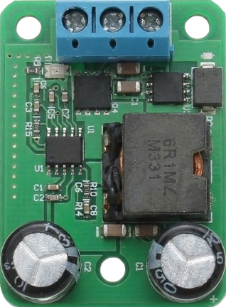
The DC-DC Buck Step Down Synchronous Rectification Power Module is a highly efficient voltage regulator designed to step down a higher input voltage to a lower output voltage. It utilizes synchronous rectification technology, which significantly reduces power loss and improves overall efficiency compared to traditional rectification methods. This module is widely used in power management applications where energy efficiency and compact design are critical.
Explore Projects Built with DC-DC Buck Step Down Synchronous Rectification Power Module


Explore Projects Built with DC-DC Buck Step Down Synchronous Rectification Power Module
Common Applications and Use Cases
- Powering low-voltage devices from higher-voltage sources (e.g., 12V to 5V conversion)
- Battery-powered systems to extend battery life
- Embedded systems and microcontroller projects
- LED drivers and lighting systems
- Industrial automation and IoT devices
Technical Specifications
Below are the key technical details of the DC-DC Buck Step Down Synchronous Rectification Power Module:
| Parameter | Specification |
|---|---|
| Input Voltage Range | 4.5V to 28V |
| Output Voltage Range | 0.8V to 20V (adjustable) |
| Output Current | Up to 5A |
| Efficiency | Up to 95% |
| Switching Frequency | 150kHz to 1MHz |
| Operating Temperature | -40°C to +85°C |
| Dimensions | Typically 22mm x 17mm x 4mm |
Pin Configuration and Descriptions
The module typically has the following pinout:
| Pin Name | Description |
|---|---|
| VIN | Input voltage pin. Connect to the positive terminal of the input power source. |
| GND | Ground pin. Connect to the negative terminal of the input power source. |
| VOUT | Output voltage pin. Provides the regulated output voltage. |
| EN | Enable pin. Pull high to enable the module; pull low to disable it. |
| ADJ | Voltage adjustment pin. Used to set the output voltage (via a potentiometer). |
Usage Instructions
How to Use the Component in a Circuit
Connect the Input Voltage:
- Connect the VIN pin to the positive terminal of your input power source.
- Connect the GND pin to the negative terminal of your input power source.
Set the Output Voltage:
- Use the onboard potentiometer (connected to the ADJ pin) to adjust the output voltage.
- Measure the output voltage at the VOUT pin using a multimeter while adjusting the potentiometer.
Connect the Load:
- Connect your load (e.g., microcontroller, LED, or other devices) to the VOUT and GND pins.
Enable the Module:
- Ensure the EN pin is pulled high (or left floating if internally pulled up) to enable the module.
Verify Connections:
- Double-check all connections to ensure proper polarity and secure wiring.
Important Considerations and Best Practices
- Input Voltage Range: Ensure the input voltage is within the specified range (4.5V to 28V). Exceeding this range may damage the module.
- Heat Dissipation: For high current loads, consider adding a heatsink or improving airflow to prevent overheating.
- Output Voltage Adjustment: Be cautious when adjusting the potentiometer to avoid setting the output voltage too high for your load.
- Capacitor Placement: Place input and output capacitors close to the module to reduce noise and improve stability.
- Load Current: Do not exceed the maximum output current (5A) to avoid damaging the module.
Example: Using with an Arduino UNO
The DC-DC Buck Step Down Module can be used to power an Arduino UNO from a 12V power source by stepping down the voltage to 5V. Below is an example circuit and code:
Circuit Connections
- Connect the 12V power source to the VIN and GND pins of the module.
- Adjust the output voltage to 5V using the potentiometer.
- Connect the VOUT pin of the module to the 5V pin of the Arduino UNO.
- Connect the GND pin of the module to the GND pin of the Arduino UNO.
Example Code
// Example code to blink an LED using Arduino UNO powered by the DC-DC module

const int ledPin = 13; // Pin connected to the onboard LED

void setup() {
  pinMode(ledPin, OUTPUT); // Set the LED pin as an output
}

void loop() {
  digitalWrite(ledPin, HIGH); // Turn the LED on
  delay(1000);                // Wait for 1 second
  digitalWrite(ledPin, LOW);  // Turn the LED off
  delay(1000);                // Wait for 1 second
}
Troubleshooting and FAQs
Common Issues and Solutions
No Output Voltage:
- Cause: The EN pin is pulled low or not connected.
- Solution: Ensure the EN pin is pulled high or left floating.
Output Voltage is Incorrect:
- Cause: The potentiometer is not adjusted correctly.
- Solution: Use a multimeter to measure and adjust the output voltage.
Module Overheating:
- Cause: Excessive load current or poor heat dissipation.
- Solution: Reduce the load current or add a heatsink to the module.
Noise or Instability:
- Cause: Insufficient input/output capacitors or poor wiring.
- Solution: Add low-ESR capacitors close to the module and use short, thick wires.
FAQs
Q: Can this module be used to charge batteries?
A: Yes, but ensure the output voltage and current are set appropriately for the battery type. Use additional circuitry for proper charging control.
Q: Is the module protected against reverse polarity?
A: Most modules do not have reverse polarity protection. Always double-check connections before powering the module.
Q: Can I use this module with a solar panel?
A: Yes, as long as the input voltage from the solar panel is within the module's input range. Add a capacitor to stabilize the input voltage if needed.