How to Use ESP32-S3 WROOM N16R8 CAM: Examples, Pinouts, and Specs
Introduction
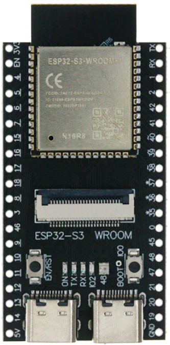
The ESP32-S3 WROOM N16R8 CAM is a powerful Wi-Fi and Bluetooth-enabled microcontroller module designed for IoT, AI, and camera-based applications. It integrates the ESP32-S3 chip, which features a dual-core Xtensa LX7 processor, 16 MB of flash memory, 8 MB of PSRAM, and a built-in camera interface. This module is ideal for applications requiring image processing, machine learning, and wireless connectivity.
Explore Projects Built with ESP32-S3 WROOM N16R8 CAM
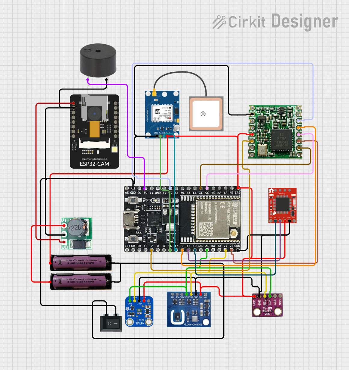

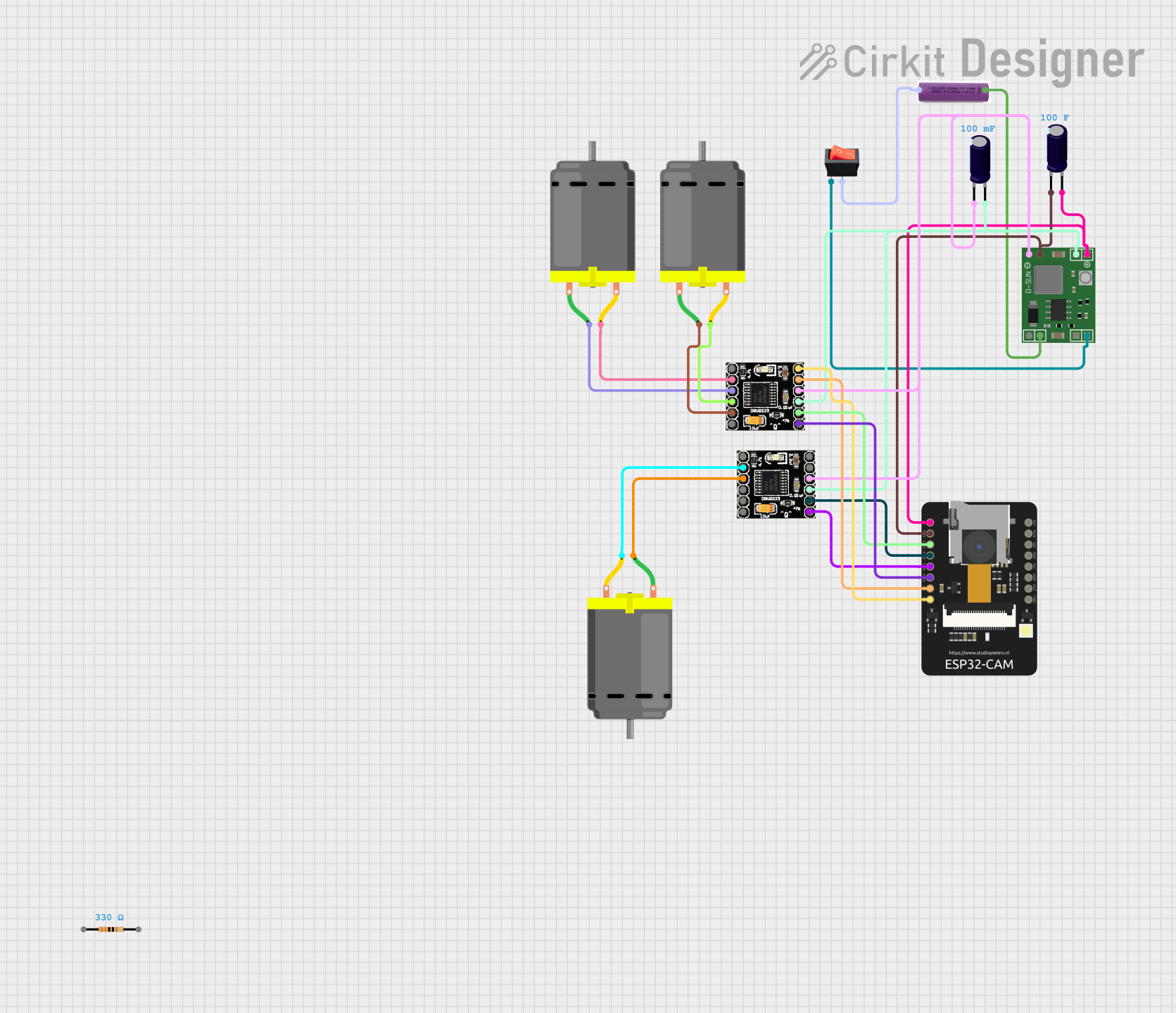

Explore Projects Built with ESP32-S3 WROOM N16R8 CAM
Common Applications and Use Cases
- Smart security cameras
- IoT devices with image recognition
- AI-powered edge computing
- Home automation systems
- Wireless video streaming
- Face detection and recognition systems
Technical Specifications
Key Technical Details
| Parameter | Specification |
|---|---|
| Microcontroller | ESP32-S3 (Xtensa LX7 dual-core CPU) |
| Flash Memory | 16 MB |
| PSRAM | 8 MB |
| Wireless Connectivity | Wi-Fi 802.11 b/g/n, Bluetooth 5.0 |
| Operating Voltage | 3.3 V |
| GPIO Pins | 45 |
| Camera Interface | Supported (DVP and I2C) |
| AI Acceleration | Vector instructions for ML workloads |
| Operating Temperature | -40°C to 85°C |
| Dimensions | 18 mm x 25.5 mm x 3.1 mm |
Pin Configuration and Descriptions
| Pin Name | Function | Description |
|---|---|---|
| 3V3 | Power Supply | 3.3 V power input |
| GND | Ground | Ground connection |
| GPIO0 | Boot Mode / General Purpose I/O | Used for boot mode selection or GPIO |
| GPIO1 | UART TX | UART transmit pin |
| GPIO2 | UART RX | UART receive pin |
| GPIO21 | I2C SDA | Data line for I2C communication |
| GPIO22 | I2C SCL | Clock line for I2C communication |
| GPIO33 | Camera PCLK | Pixel clock for camera interface |
| GPIO34 | Camera VSYNC | Vertical sync for camera interface |
| GPIO35 | Camera HREF | Horizontal reference for camera interface |
| GPIO36 | Camera D0 | Camera data line 0 |
| GPIO37 | Camera D1 | Camera data line 1 |
| GPIO38 | Camera D2 | Camera data line 2 |
| GPIO39 | Camera D3 | Camera data line 3 |
| GPIO40 | Camera D4 | Camera data line 4 |
| GPIO41 | Camera D5 | Camera data line 5 |
| GPIO42 | Camera D6 | Camera data line 6 |
| GPIO43 | Camera D7 | Camera data line 7 |
Usage Instructions
How to Use the ESP32-S3 WROOM N16R8 CAM in a Circuit
- Power Supply: Connect the 3V3 pin to a stable 3.3 V power source and GND to ground.
- Camera Interface: Connect the camera module to the appropriate GPIO pins (e.g., PCLK, VSYNC, HREF, and D0-D7).
- Programming: Use the UART pins (GPIO1 and GPIO2) or USB interface for programming the module.
- I2C Communication: Connect I2C devices to GPIO21 (SDA) and GPIO22 (SCL) for peripherals like sensors.
- Wi-Fi and Bluetooth: Configure wireless connectivity using the ESP-IDF or Arduino IDE.
Important Considerations and Best Practices
- Ensure the power supply is stable and within the operating voltage range (3.3 V).
- Use appropriate pull-up resistors for I2C communication lines.
- Avoid connecting high-current devices directly to GPIO pins; use transistors or relays.
- When using the camera interface, ensure the camera module is compatible with the ESP32-S3.
- Use the ESP-IDF or Arduino IDE for programming. Install the necessary libraries for camera and AI functionalities.
Example Code for Capturing an Image with Arduino IDE
#include "esp_camera.h"

// Define camera pins for the ESP32-S3 WROOM N16R8 CAM
#define PWDN_GPIO_NUM    -1 // Power down pin not used
#define RESET_GPIO_NUM   -1 // Reset pin not used
#define XCLK_GPIO_NUM    0  // XCLK pin
#define SIOD_GPIO_NUM    21 // I2C SDA
#define SIOC_GPIO_NUM    22 // I2C SCL
#define Y9_GPIO_NUM      36 // Camera D0
#define Y8_GPIO_NUM      37 // Camera D1
#define Y7_GPIO_NUM      38 // Camera D2
#define Y6_GPIO_NUM      39 // Camera D3
#define Y5_GPIO_NUM      40 // Camera D4
#define Y4_GPIO_NUM      41 // Camera D5
#define Y3_GPIO_NUM      42 // Camera D6
#define Y2_GPIO_NUM      43 // Camera D7
#define VSYNC_GPIO_NUM   34 // VSYNC pin
#define HREF_GPIO_NUM    35 // HREF pin
#define PCLK_GPIO_NUM    33 // PCLK pin

void setup() {
  Serial.begin(115200);

  // Camera configuration
  camera_config_t config;
  config.ledc_channel = LEDC_CHANNEL_0;
  config.ledc_timer = LEDC_TIMER_0;
  config.pin_d0 = Y9_GPIO_NUM;
  config.pin_d1 = Y8_GPIO_NUM;
  config.pin_d2 = Y7_GPIO_NUM;
  config.pin_d3 = Y6_GPIO_NUM;
  config.pin_d4 = Y5_GPIO_NUM;
  config.pin_d5 = Y4_GPIO_NUM;
  config.pin_d6 = Y3_GPIO_NUM;
  config.pin_d7 = Y2_GPIO_NUM;
  config.pin_xclk = XCLK_GPIO_NUM;
  config.pin_pclk = PCLK_GPIO_NUM;
  config.pin_vsync = VSYNC_GPIO_NUM;
  config.pin_href = HREF_GPIO_NUM;
  config.pin_sscb_sda = SIOD_GPIO_NUM;
  config.pin_sscb_scl = SIOC_GPIO_NUM;
  config.pin_pwdn = PWDN_GPIO_NUM;
  config.pin_reset = RESET_GPIO_NUM;
  config.xclk_freq_hz = 20000000; // 20 MHz
  config.pixel_format = PIXFORMAT_JPEG; // JPEG format

  // Initialize the camera
  if (esp_camera_init(&config) != ESP_OK) {
    Serial.println("Camera initialization failed!");
    return;
  }
  Serial.println("Camera initialized successfully.");
}

void loop() {
  // Capture an image
  camera_fb_t *fb = esp_camera_fb_get();
  if (!fb) {
    Serial.println("Failed to capture image.");
    return;
  }

  // Print image size
  Serial.printf("Captured image size: %d bytes\n", fb->len);

  // Return the frame buffer to the driver
  esp_camera_fb_return(fb);

  delay(5000); // Wait 5 seconds before capturing the next image
}
Troubleshooting and FAQs
Common Issues and Solutions
Camera Initialization Fails:
- Ensure the camera module is properly connected to the GPIO pins.
- Verify that the camera module is compatible with the ESP32-S3.
Wi-Fi Connection Issues:
- Check the Wi-Fi credentials in your code.
- Ensure the ESP32-S3 is within range of the Wi-Fi router.
Power Supply Problems:
- Use a stable 3.3 V power source with sufficient current capacity.
- Avoid powering the module directly from USB if additional peripherals are connected.
Image Capture Fails:
- Verify the camera configuration in the code.
- Ensure the camera module is functioning correctly.
FAQs
Can I use this module with the Arduino IDE? Yes, the ESP32-S3 WROOM N16R8 CAM is compatible with the Arduino IDE. Install the ESP32 board package to get started.
What is the maximum resolution supported by the camera interface? The module supports resolutions up to 1600x1200 (UXGA), depending on the camera module used.
Does the module support AI processing? Yes, the ESP32-S3 includes vector instructions optimized for AI and machine learning tasks.