How to Use UCC27524: Examples, Pinouts, and Specs
Introduction
The UCC27524, manufactured by Texas Instruments, is a high-speed, dual-channel, low-side gate driver designed to drive MOSFETs and IGBTs in power applications. It is optimized for high-frequency switching and features fast rise and fall times, low propagation delay, and a wide supply voltage range. This makes it ideal for applications requiring efficient and reliable switching performance.
Explore Projects Built with UCC27524


Explore Projects Built with UCC27524
Common Applications
- Switch-mode power supplies (SMPS)
- DC-DC converters
- Motor drives
- Solar inverters
- Uninterruptible power supplies (UPS)
Technical Specifications
Key Features
- Supply Voltage Range (VDD): 4.5 V to 18 V
- Peak Source Current: 5 A
- Peak Sink Current: 5 A
- Propagation Delay: 13 ns (typical)
- Rise Time: 7 ns (typical)
- Fall Time: 6 ns (typical)
- Operating Temperature Range: -40°C to 140°C
- Input Threshold Type: CMOS/TTL compatible
- Output Channels: 2 (independent or inverting/non-inverting configuration)
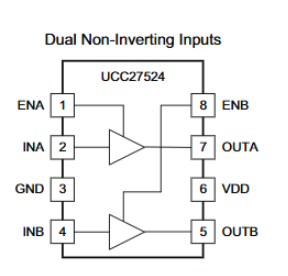
Pin Configuration and Descriptions
The UCC27524 is available in an 8-pin SOIC (D) or VSSOP (DGK) package. Below is the pinout and description:
| Pin | Name | Type | Description |
|---|---|---|---|
| 1 | IN1 | Input | Input signal for Channel 1 (CMOS/TTL compatible). |
| 2 | IN2 | Input | Input signal for Channel 2 (CMOS/TTL compatible). |
| 3 | GND | Ground | Ground reference for the device. |
| 4 | OUT2 | Output | Output signal for Channel 2. |
| 5 | VDD | Power Supply | Supply voltage input (4.5 V to 18 V). |
| 6 | OUT1 | Output | Output signal for Channel 1. |
| 7 | EN | Enable Input | Enable pin for both channels (active high). |
| 8 | NC | No Connection | No internal connection; can be left floating or connected to GND. |
Usage Instructions
Using the UCC27524 in a Circuit
Power Supply:
- Connect the VDD pin to a stable power supply within the range of 4.5 V to 18 V.
- Decouple the VDD pin with a low-ESR ceramic capacitor (e.g., 1 µF) placed close to the pin to minimize noise.
Input Signals:
- Apply CMOS/TTL-compatible signals to the IN1 and IN2 pins to control the outputs.
- Ensure the input signals do not exceed the VDD voltage level.
Output Connections:
- Connect the OUT1 and OUT2 pins to the gate of the MOSFETs or IGBTs.
- Use a gate resistor (e.g., 10 Ω to 100 Ω) to limit the inrush current and reduce ringing.
Enable Pin:
- The EN pin must be pulled high to enable the outputs. If unused, connect it to VDD.
Grounding:
- Connect the GND pin to the system ground. Ensure a low-impedance ground connection to minimize noise.
Important Considerations
- Thermal Management: Ensure adequate heat dissipation, especially in high-frequency or high-current applications.
- PCB Layout: Minimize trace lengths for the output pins to reduce parasitic inductance and improve switching performance.
- Input Signal Integrity: Use clean, noise-free input signals to avoid false triggering.
Example: Driving a MOSFET with Arduino UNO
The UCC27524 can be used with an Arduino UNO to drive a MOSFET. Below is an example circuit and code:
Circuit Description
- Connect the Arduino digital pin (e.g., D3) to the IN1 pin of the UCC27524.
- Connect the OUT1 pin to the gate of the MOSFET.
- Connect the source of the MOSFET to GND and the drain to the load.
- Connect the EN pin to VDD to enable the driver.
Arduino Code
// Example code to drive a MOSFET using UCC27524 and Arduino UNO

#define MOSFET_PIN 3  // Define the Arduino pin connected to UCC27524 IN1

void setup() {
  pinMode(MOSFET_PIN, OUTPUT);  // Set the MOSFET control pin as output
}

void loop() {
  digitalWrite(MOSFET_PIN, HIGH);  // Turn the MOSFET ON
  delay(1000);                     // Wait for 1 second
  digitalWrite(MOSFET_PIN, LOW);   // Turn the MOSFET OFF
  delay(1000);                     // Wait for 1 second
}
Troubleshooting and FAQs
Common Issues and Solutions
| Issue | Possible Cause | Solution |
|---|---|---|
| No output from OUT1 or OUT2 | EN pin not connected or pulled low | Ensure the EN pin is connected to VDD or a high logic level. |
| Excessive heating of the UCC27524 | High switching frequency or insufficient cooling | Use a heatsink or improve PCB thermal design. |
| Output signal distortion or ringing | Long PCB traces or no gate resistor | Minimize trace lengths and use a gate resistor (10 Ω to 100 Ω). |
| Device not functioning as expected | Incorrect power supply voltage | Verify that the VDD voltage is within the 4.5 V to 18 V range. |
| False triggering of outputs | Noisy input signals | Use proper signal conditioning or shielding to reduce noise. |
FAQs
Can the UCC27524 drive high-side MOSFETs?
- No, the UCC27524 is a low-side driver and is not suitable for directly driving high-side MOSFETs.
What is the maximum switching frequency?
- The UCC27524 can operate at frequencies up to several MHz, depending on the load capacitance and power dissipation.
Can I leave unused input pins floating?
- No, unused input pins should be tied to GND or VDD to prevent undefined behavior.
Is the UCC27524 suitable for driving parallel MOSFETs?
- Yes, but ensure proper gate resistors are used to balance the gate drive currents.
By following this documentation, users can effectively integrate the UCC27524 into their designs for high-speed, reliable switching applications.