How to Use pilot led yellow: Examples, Pinouts, and Specs
Introduction
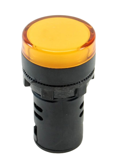
The Arduino Yellow Pilot LED (Part ID: UNO) is a yellow light-emitting diode (LED) designed for use as an indicator light in control panels and electronic devices. It is commonly used to show the status of a circuit or system, providing a visual indication of power, activity, or other states. This LED is an essential component in various applications, including DIY electronics projects, industrial control systems, and educational kits.
Explore Projects Built with pilot led yellow
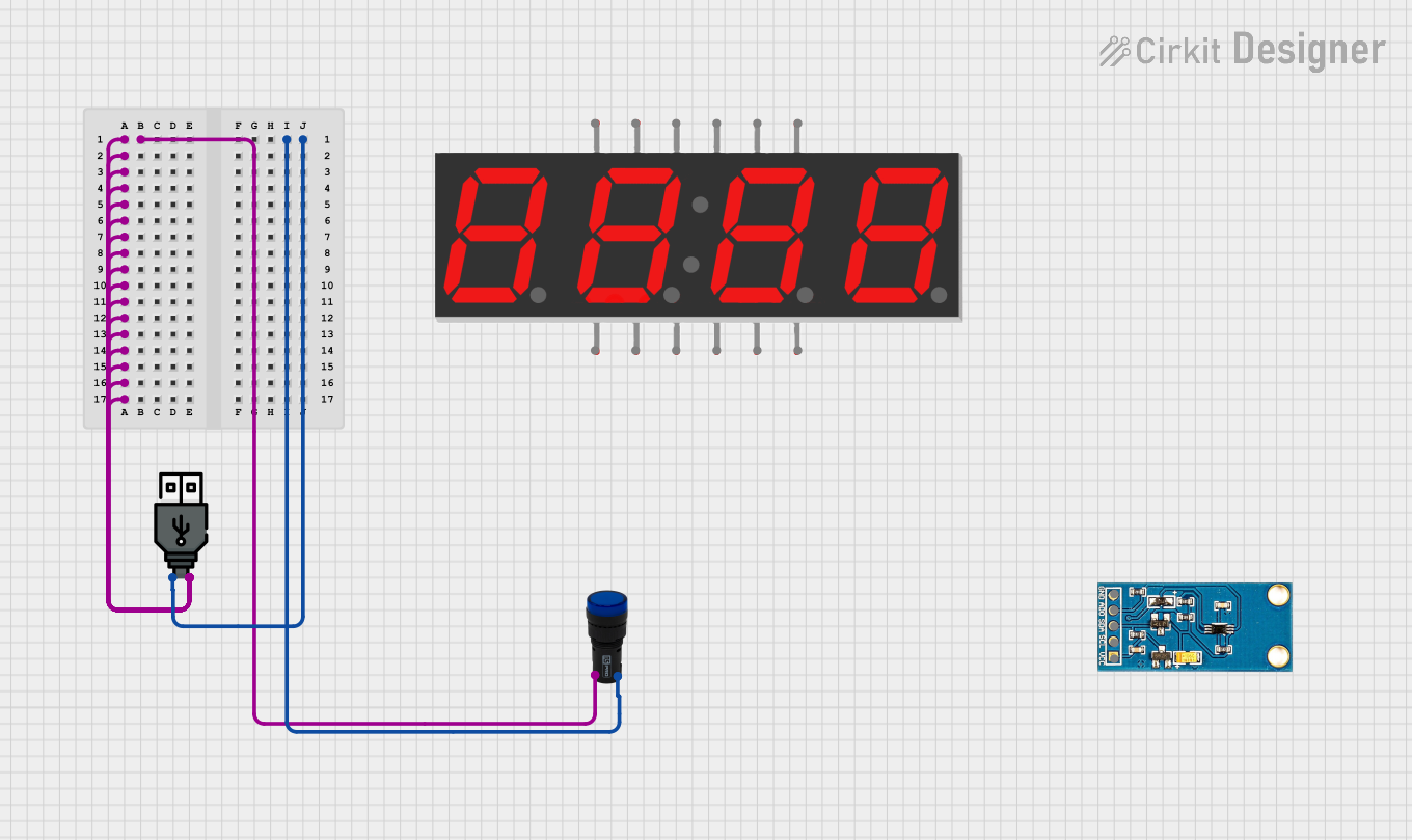
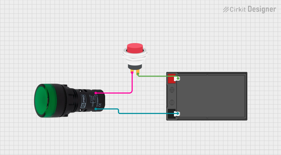
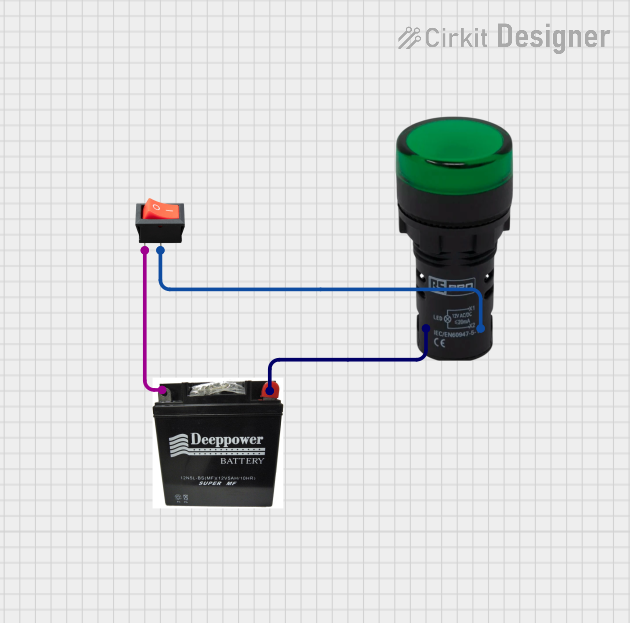
Explore Projects Built with pilot led yellow
Technical Specifications
Key Technical Details
| Parameter | Value |
|---|---|
| Manufacturer | Arduino |
| Part ID | UNO |
| Color | Yellow |
| Forward Voltage | 2.0V - 2.2V |
| Forward Current | 20mA |
| Power Rating | 44mW |
| Wavelength | 590nm |
| Viewing Angle | 30 degrees |
| Package Type | 5mm (T-1 3/4) |
Pin Configuration and Descriptions
| Pin Number | Pin Name | Description |
|---|---|---|
| 1 | Anode | Positive terminal (longer lead) |
| 2 | Cathode | Negative terminal (shorter lead) |
Usage Instructions
How to Use the Component in a Circuit
Identify the Anode and Cathode:
- The longer lead is the Anode (positive terminal).
- The shorter lead is the Cathode (negative terminal).
Connect the LED to a Resistor:
- To prevent damage, always use a current-limiting resistor in series with the LED.
- Calculate the resistor value using Ohm's Law: ( R = \frac{V_{supply} - V_{forward}}{I_{forward}} )
- For a 5V supply and a forward voltage of 2.1V, with a forward current of 20mA: ( R = \frac{5V - 2.1V}{0.02A} = 145\Omega ) (use the nearest standard resistor value, e.g., 150Ω).
Connect to Arduino UNO:
- Connect the Anode to a digital I/O pin (e.g., pin 13) on the Arduino UNO.
- Connect the Cathode to the ground (GND) through the current-limiting resistor.
Important Considerations and Best Practices
- Polarity: Ensure correct polarity when connecting the LED. Reversing the connections can damage the LED.
- Current Limiting: Always use a current-limiting resistor to prevent excessive current flow, which can damage the LED.
- Heat Dissipation: Ensure adequate ventilation to prevent overheating, especially in high-power applications.
Example Code for Arduino UNO
// Example code to blink a yellow LED connected to pin 13 on Arduino UNO

const int ledPin = 13; // Pin number where the LED is connected

void setup() {
  pinMode(ledPin, OUTPUT); // Set the LED pin as an output
}

void loop() {
  digitalWrite(ledPin, HIGH); // Turn the LED on
  delay(1000); // Wait for 1 second
  digitalWrite(ledPin, LOW); // Turn the LED off
  delay(1000); // Wait for 1 second
}
Troubleshooting and FAQs
Common Issues Users Might Face
LED Does Not Light Up:
- Solution: Check the polarity of the LED. Ensure the Anode is connected to the positive voltage and the Cathode to the ground.
- Solution: Verify the current-limiting resistor value. Ensure it is not too high, which can prevent the LED from lighting up.
LED is Dim:
- Solution: Check the resistor value. A higher resistance can reduce the current and dim the LED.
- Solution: Ensure the power supply voltage is sufficient to forward bias the LED.
LED Flickers:
- Solution: Check for loose connections or intermittent contacts in the circuit.
- Solution: Ensure the power supply is stable and not fluctuating.
FAQs
Q: Can I connect the LED directly to the Arduino without a resistor?
- A: No, connecting the LED directly without a resistor can cause excessive current flow and damage both the LED and the Arduino.
Q: What is the maximum current the LED can handle?
- A: The maximum forward current for the LED is 20mA. Exceeding this can damage the LED.
Q: Can I use the LED with a 3.3V supply?
- A: Yes, you can use the LED with a 3.3V supply, but you will need to recalculate the current-limiting resistor value accordingly.
This documentation provides a comprehensive guide to using the Arduino Yellow Pilot LED (Part ID: UNO). Whether you are a beginner or an experienced user, following these instructions and best practices will help you effectively integrate this component into your projects.