How to Use Memory Chip EEPROM AT24C02 I2C: Examples, Pinouts, and Specs
Introduction
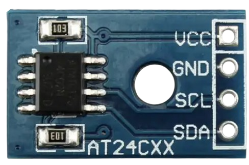
The AT24C02 is a 2K-bit Electrically Erasable Programmable Read-Only Memory (EEPROM) manufactured by EEPROM. It communicates using the I2C (Inter-Integrated Circuit) protocol, making it easy to interface with microcontrollers and other digital devices. This non-volatile memory chip retains data even when power is removed, making it ideal for applications requiring persistent data storage.
Explore Projects Built with Memory Chip EEPROM AT24C02 I2C


Explore Projects Built with Memory Chip EEPROM AT24C02 I2C
Common Applications and Use Cases
- Data logging in embedded systems
- Configuration and calibration data storage
- Storing user preferences in consumer electronics
- Non-volatile memory for microcontroller-based projects
- Industrial automation systems requiring reliable data retention
Technical Specifications
The AT24C02 is designed for low-power, high-reliability applications. Below are its key technical specifications:
| Parameter | Value |
|---|---|
| Memory Size | 2 Kbits (256 bytes) |
| Interface | I2C (2-wire) |
| Operating Voltage Range | 1.7V to 5.5V |
| Maximum Clock Frequency | 1 MHz (Fast Mode Plus) |
| Write Cycle Time | 5 ms (typical) |
| Data Retention | 100 years (typical) |
| Endurance | 1,000,000 write/erase cycles |
| Operating Temperature | -40°C to +85°C |
| Package Types | 8-pin SOIC, TSSOP, PDIP |
Pin Configuration and Descriptions
The AT24C02 is an 8-pin device. Below is the pinout and description:
| Pin Number | Pin Name | Description |
|---|---|---|
| 1 | A0 | Address input bit 0 (used for I2C slave address selection) |
| 2 | A1 | Address input bit 1 (used for I2C slave address selection) |
| 3 | A2 | Address input bit 2 (used for I2C slave address selection) |
| 4 | GND | Ground (0V reference) |
| 5 | SDA | Serial Data Line (I2C bidirectional data line) |
| 6 | SCL | Serial Clock Line (I2C clock input) |
| 7 | WP | Write Protect (active high; disables write operations when tied to VCC) |
| 8 | VCC | Power supply (1.7V to 5.5V) |
Usage Instructions
How to Use the AT24C02 in a Circuit
- Power Supply: Connect the VCC pin to a power source (1.7V to 5.5V) and the GND pin to ground.
- I2C Connections:
- Connect the SDA pin to the microcontroller's I2C data line.
- Connect the SCL pin to the microcontroller's I2C clock line.
- Use pull-up resistors (typically 4.7kΩ to 10kΩ) on both SDA and SCL lines.
- Address Selection: Configure the A0, A1, and A2 pins to set the I2C slave address. These pins can be tied to GND or VCC.
- Write Protection: If write operations are not required, connect the WP pin to VCC to enable write protection.
- Bypass Capacitor: Place a 0.1µF ceramic capacitor close to the VCC and GND pins for power supply decoupling.
Example: Interfacing with Arduino UNO
Below is an example of how to interface the AT24C02 with an Arduino UNO to write and read data.
Circuit Diagram
- Connect:
- SDA (pin 5) to Arduino A4
- SCL (pin 6) to Arduino A5
- VCC (pin 8) to 5V
- GND (pin 4) to GND
- A0, A1, A2 to GND (I2C address: 0x50)
Arduino Code
#include <Wire.h> // Include the Wire library for I2C communication

#define EEPROM_I2C_ADDRESS 0x50 // I2C address of AT24C02 (A0, A1, A2 = GND)

void setup() {
  Wire.begin(); // Initialize I2C communication
  Serial.begin(9600); // Initialize serial communication for debugging
  writeEEPROM(0x00, 42); // Write the value 42 to memory address 0x00
  delay(10); // Wait for the write cycle to complete
  int value = readEEPROM(0x00); // Read the value from memory address 0x00
  Serial.print("Read value: ");
  Serial.println(value); // Print the read value to the Serial Monitor
}

void loop() {
  // Main loop does nothing
}

// Function to write a byte to the EEPROM
void writeEEPROM(int address, byte data) {
  Wire.beginTransmission(EEPROM_I2C_ADDRESS); // Start I2C communication
  Wire.write((byte)address); // Send memory address
  Wire.write(data); // Send data byte
  Wire.endTransmission(); // End I2C communication
  delay(5); // Allow time for the write cycle to complete
}

// Function to read a byte from the EEPROM
byte readEEPROM(int address) {
  Wire.beginTransmission(EEPROM_I2C_ADDRESS); // Start I2C communication
  Wire.write((byte)address); // Send memory address
  Wire.endTransmission(); // End transmission to set the address pointer
  Wire.requestFrom(EEPROM_I2C_ADDRESS, 1); // Request 1 byte of data
  if (Wire.available()) {
    return Wire.read(); // Read and return the received byte
  }
  return 0; // Return 0 if no data is available
}
Important Considerations and Best Practices
- Pull-Up Resistors: Ensure proper pull-up resistors are used on the SDA and SCL lines for reliable I2C communication.
- Write Protection: Use the WP pin to prevent accidental overwriting of data.
- Write Cycle Time: Avoid writing to the EEPROM too frequently to prevent wear-out. The chip supports up to 1,000,000 write cycles.
- Address Conflicts: Ensure no other I2C devices on the bus share the same address as the AT24C02.
Troubleshooting and FAQs
Common Issues and Solutions
No Communication with the EEPROM
- Cause: Incorrect I2C address or wiring.
- Solution: Verify the A0, A1, and A2 pin connections and ensure the correct I2C address is used in the code.
Data Not Retained After Power Loss
- Cause: Write operation not completed before power loss.
- Solution: Ensure a delay of at least 5ms after a write operation to allow the write cycle to complete.
Corrupted Data
- Cause: Noise on the I2C lines or insufficient pull-up resistance.
- Solution: Use proper pull-up resistors (4.7kΩ to 10kΩ) and ensure clean wiring.
Write Operations Failing
- Cause: WP pin tied to VCC.
- Solution: Tie the WP pin to GND to enable write operations.
FAQs
Q1: Can I use the AT24C02 with a 3.3V microcontroller?
Yes, the AT24C02 operates within a voltage range of 1.7V to 5.5V, making it compatible with 3.3V systems.
Q2: How do I calculate the I2C address?
The I2C address is determined by the state of the A0, A1, and A2 pins. For example, if all are tied to GND, the address is 0x50.
Q3: Can I connect multiple AT24C02 chips on the same I2C bus?
Yes, you can connect up to 8 AT24C02 chips by configuring the A0, A1, and A2 pins to unique combinations.
Q4: What happens if I exceed the write cycle limit?
Exceeding the 1,000,000 write cycle limit may result in unreliable data storage. Use wear-leveling techniques to extend the chip's lifespan.