Cirkit Designer Logo
Cirkit Designer
Your all-in-one circuit design IDE
Home / 
Component Documentation

How to Use LTC3588: Examples, Pinouts, and Specs

Image of LTC3588
Cirkit Designer LogoDesign with LTC3588 in Cirkit Designer

Introduction

The LTC3588 is a versatile energy harvesting power management integrated circuit (PMIC) designed to efficiently convert and manage power from various energy sources such as piezoelectric, solar, or magnetic transducers. It incorporates a low-loss full-wave bridge rectifier, a high-efficiency buck converter, and a battery charger, making it ideal for low-power applications where energy harvesting is essential. Common applications include wireless sensors, environmental monitoring devices, and wearable technology.

Explore Projects Built with LTC3588

Use Cirkit Designer to design, explore, and prototype these projects online. Some projects support real-time simulation. Click "Open Project" to start designing instantly!
LM358 Op-Amp and Transistor Amplifier Circuit
Image of Lab 3 wiring diagram: A project utilizing LTC3588 in a practical application
The circuit includes an LM358 op-amp, NPN and PNP transistors, and resistors that are likely configured for signal processing or control applications. The op-amp is powered, and the transistors are arranged for switching or amplification, with resistors providing biasing and current limiting. The exact functionality is unclear without embedded code or further context.
Cirkit Designer LogoOpen Project in Cirkit Designer
Battery-Powered DC Motor Control with USB Charging and LED Indicator
Image of lumantas: A project utilizing LTC3588 in a practical application
This circuit is designed to charge a Li-ion battery and power a DC motor and a 12V LED. The TP4056 module manages the battery charging process, while the PowerBoost 1000 and MT3608 boost converters step up the voltage to drive the motor and LED, respectively. Two rocker switches control the power flow to the LED and the charging circuit.
Cirkit Designer LogoOpen Project in Cirkit Designer
Cellular-Enabled IoT Device with Real-Time Clock and Power Management
Image of LRCM PHASE 2 BASIC: A project utilizing LTC3588 in a practical application
This circuit features a LilyGo-SIM7000G module for cellular communication and GPS functionality, interfaced with an RTC DS3231 for real-time clock capabilities. It includes voltage sensing through two voltage sensor modules, and uses an 8-channel opto-coupler for isolating different parts of the circuit. Power management is handled by a buck converter connected to a DC power source and batteries, with a fuse for protection and a rocker switch for on/off control. Additionally, there's an LED for indication purposes.
Cirkit Designer LogoOpen Project in Cirkit Designer
Multi-Stage Voltage Regulation and Indicator LED Circuit
Image of Subramanyak_Power_Circuit: A project utilizing LTC3588 in a practical application
This circuit is designed for power management, featuring buck and boost converters for voltage adjustment, and linear regulators for stable voltage output. It includes LEDs for status indication, and terminal blocks for external connections.
Cirkit Designer LogoOpen Project in Cirkit Designer

Explore Projects Built with LTC3588

Use Cirkit Designer to design, explore, and prototype these projects online. Some projects support real-time simulation. Click "Open Project" to start designing instantly!
Image of Lab 3 wiring diagram: A project utilizing LTC3588 in a practical application
LM358 Op-Amp and Transistor Amplifier Circuit
The circuit includes an LM358 op-amp, NPN and PNP transistors, and resistors that are likely configured for signal processing or control applications. The op-amp is powered, and the transistors are arranged for switching or amplification, with resistors providing biasing and current limiting. The exact functionality is unclear without embedded code or further context.
Cirkit Designer LogoOpen Project in Cirkit Designer
Image of lumantas: A project utilizing LTC3588 in a practical application
Battery-Powered DC Motor Control with USB Charging and LED Indicator
This circuit is designed to charge a Li-ion battery and power a DC motor and a 12V LED. The TP4056 module manages the battery charging process, while the PowerBoost 1000 and MT3608 boost converters step up the voltage to drive the motor and LED, respectively. Two rocker switches control the power flow to the LED and the charging circuit.
Cirkit Designer LogoOpen Project in Cirkit Designer
Image of LRCM PHASE 2 BASIC: A project utilizing LTC3588 in a practical application
Cellular-Enabled IoT Device with Real-Time Clock and Power Management
This circuit features a LilyGo-SIM7000G module for cellular communication and GPS functionality, interfaced with an RTC DS3231 for real-time clock capabilities. It includes voltage sensing through two voltage sensor modules, and uses an 8-channel opto-coupler for isolating different parts of the circuit. Power management is handled by a buck converter connected to a DC power source and batteries, with a fuse for protection and a rocker switch for on/off control. Additionally, there's an LED for indication purposes.
Cirkit Designer LogoOpen Project in Cirkit Designer
Image of Subramanyak_Power_Circuit: A project utilizing LTC3588 in a practical application
Multi-Stage Voltage Regulation and Indicator LED Circuit
This circuit is designed for power management, featuring buck and boost converters for voltage adjustment, and linear regulators for stable voltage output. It includes LEDs for status indication, and terminal blocks for external connections.
Cirkit Designer LogoOpen Project in Cirkit Designer

Technical Specifications

Key Features

  • Integrated low-loss full-wave bridge rectifier
  • High-efficiency synchronous buck converter
  • Programmable output voltages
  • Input voltage range: 2.7V to 20V
  • Output voltage range: 1.8V to 5V
  • Quiescent current: 950nA (no load)
  • Battery charging capability with programmable float voltage

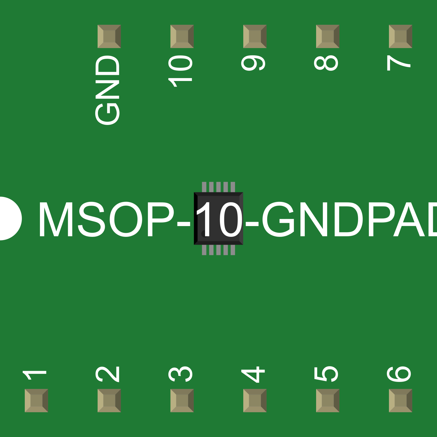
Pin Configuration and Descriptions

Pin Number Name Description
1 VIN Input voltage from energy source
2 GND Ground reference
3 VOUT Regulated output voltage
4 VSTORE Storage element connection
5 VFB Feedback voltage pin for output regulation
6 CTRL Control input for enabling/disabling the converter
7 NC No connection (reserved for future use)
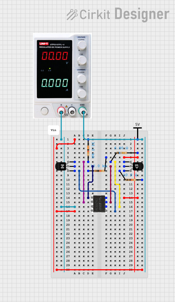
Usage Instructions

Connecting the LTC3588 to a Circuit

  1. Connect the energy source to the VIN and GND pins.
  2. Attach a storage element (battery or capacitor) to the VSTORE pin.
  3. Set the desired output voltage by connecting a resistor divider from VOUT to VFB to GND.
  4. Enable the converter by pulling the CTRL pin high.

Important Considerations and Best Practices

  • Ensure that the input voltage does not exceed the maximum rating of 20V.
  • Select the storage element (battery or capacitor) based on the application's energy requirements.
  • Use a low ESR capacitor at the output to minimize voltage ripple.
  • Place the LTC3588 close to the energy source and storage element to reduce losses.
  • For optimal performance, carefully select external components according to the manufacturer's recommendations.

Troubleshooting and FAQs

Common Issues

  • No Output Voltage: Ensure that the energy source is connected correctly and is providing sufficient voltage. Check the CTRL pin is high to enable the converter.
  • Output Voltage Too Low or High: Verify the resistor divider values connected to the VFB pin are correct for the desired output voltage.
  • Battery Not Charging: Confirm that the battery is properly connected to VSTORE and that it is within the charging voltage range.

Solutions and Tips

  • If the output voltage is unstable, check the output capacitor for proper ESR and capacitance values.
  • For issues related to battery charging, ensure that the float voltage is programmed correctly and that the battery chemistry is compatible with the LTC3588's charging profile.

FAQs

Q: Can the LTC3588 be used with solar panels? A: Yes, the LTC3588 is suitable for solar energy harvesting applications.

Q: What types of batteries can be charged with the LTC3588? A: The LTC3588 can charge various rechargeable batteries, including Li-Ion, NiMH, or lead-acid, as long as the float voltage is correctly set.

Q: How can I adjust the output voltage? A: The output voltage can be adjusted by changing the resistor values in the feedback divider network connected to the VFB pin.

Example Code for Arduino UNO

Below is an example code snippet for interfacing the LTC3588 with an Arduino UNO to monitor the output voltage.

// Define the analog pin connected to VOUT
const int analogPin = A0;

void setup() {
  // Initialize serial communication at 9600 baud rate
  Serial.begin(9600);
}

void loop() {
  // Read the voltage from the LTC3588's VOUT pin
  int sensorValue = analogRead(analogPin);
  // Convert the analog reading to voltage (assuming a 5V reference)
  float voltage = sensorValue * (5.0 / 1023.0);
  
  // Print the voltage to the Serial Monitor
  Serial.print("Output Voltage: ");
  Serial.print(voltage);
  Serial.println(" V");
  
  // Wait for a second before taking another reading
  delay(1000);
}

Remember to calibrate the voltage reading based on the specific resistor divider values used in your application. The code assumes a direct connection between VOUT and the Arduino analog input, which may require scaling if the voltage exceeds the Arduino's reference voltage.