
How to Use Teensy++ 2.0: Examples, Pinouts, and Specs
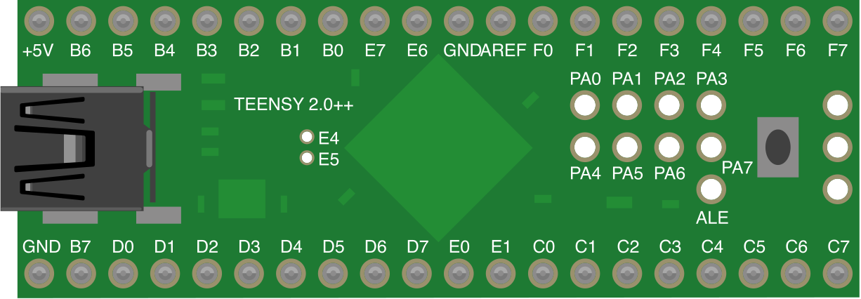
 Design with Teensy++ 2.0 in Cirkit Designer
Introduction
The Teensy++ 2.0 is a powerful and versatile microcontroller development board based on the AT90USB1286 chip. It features built-in USB support, a large number of input/output (I/O) pins, and is compatible with the Arduino IDE, making it an excellent choice for both beginners and advanced users. Its compact size and robust capabilities make it ideal for a variety of applications, including:
- Robotics and automation systems
- Interactive devices and wearables
- Data logging and sensor interfacing
- Custom USB devices (e.g., keyboards, MIDI controllers)
- Prototyping and educational projects
Explore Projects Built with Teensy++ 2.0
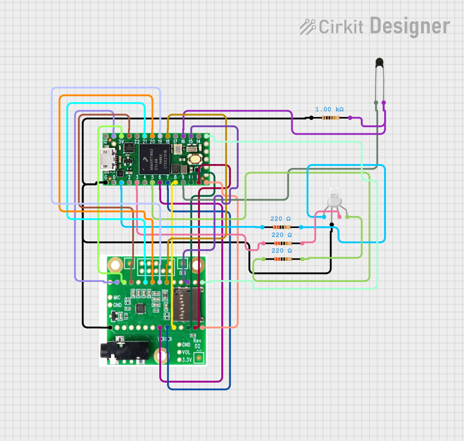 Open Project in Cirkit Designer
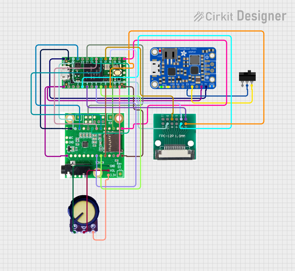 Open Project in Cirkit Designer
 Open Project in Cirkit Designer
 Open Project in Cirkit Designer
Explore Projects Built with Teensy++ 2.0
Open Project in Cirkit DesignerOpen Project in Cirkit DesignerOpen Project in Cirkit DesignerOpen Project in Cirkit DesignerTechnical Specifications
The following table outlines the key technical details of the Teensy++ 2.0:
| Specification | Details |
|---|---|
| Microcontroller | AT90USB1286 |
| Operating Voltage | 5V |
| Input Voltage (USB) | 5V |
| Clock Speed | 16 MHz |
| Flash Memory | 130 KB |
| SRAM | 8 KB |
| EEPROM | 4 KB |
| Digital I/O Pins | 46 |
| PWM Pins | 9 |
| Analog Input Pins | 8 (10-bit resolution) |
| USB Support | Yes (native USB) |
| Communication Protocols | UART, SPI, I2C |
| Dimensions | 2.0 x 0.7 inches (50.8 x 17.8 mm) |
Pin Configuration and Descriptions
The Teensy++ 2.0 has a total of 46 digital I/O pins, including 8 analog input pins. The following table provides a summary of the pin configuration:
| Pin | Function | Description |
|---|---|---|
| 0-7 | Digital I/O, PWM | General-purpose digital pins, some support PWM output |
| 8-15 | Digital I/O | General-purpose digital pins |
| 16-23 | Digital I/O, Analog Input | Can be used as digital pins or analog inputs (ADC) |
| 24-31 | Digital I/O | General-purpose digital pins |
| 32-39 | Digital I/O | General-purpose digital pins |
| 40-45 | Digital I/O | General-purpose digital pins |
| A0-A7 | Analog Input | 10-bit resolution analog input pins |
| USB | USB Data (D+, D-) | Native USB interface for programming and communication |
| GND | Ground | Ground connection |
| VIN | Input Voltage | Power input (5V from USB or external source) |
| RESET | Reset | Resets the microcontroller |
Usage Instructions
How to Use the Teensy++ 2.0 in a Circuit
Powering the Board:
- The Teensy++ 2.0 can be powered via the USB port (5V) or through the VIN pin using an external power source (5V regulated).
- Ensure the power source is stable and within the recommended voltage range.
Programming the Board:
- Install the Arduino IDE and the Teensyduino add-on for Teensy compatibility.
- Connect the Teensy++ 2.0 to your computer using a USB cable.
- Select the appropriate board and port in the Arduino IDE.
- Write your code and upload it to the board.
Connecting Peripherals:
- Use the digital I/O pins for connecting LEDs, buttons, or other digital devices.
- Use the analog input pins (A0-A7) for sensors that output analog signals.
- For communication, use the UART, SPI, or I2C pins as needed.
Important Considerations and Best Practices
- USB Communication: The Teensy++ 2.0 supports native USB communication, allowing it to emulate devices like keyboards, mice, or MIDI controllers. Use the appropriate USB libraries in your code.
- Pin Voltage Levels: Ensure that the voltage levels of connected peripherals are compatible with the 5V logic of the Teensy++ 2.0.
- Heat Management: Avoid overloading the board with excessive current. Use external power supplies for high-power peripherals.
- Bootloader Mode: If the board does not respond, press the reset button to enter bootloader mode for reprogramming.
Example Code for Arduino IDE
The following example demonstrates how to blink an LED connected to pin 13:
// Blink an LED connected to pin 13 on the Teensy++ 2.0

void setup() {
  pinMode(13, OUTPUT); // Set pin 13 as an output
}

void loop() {
  digitalWrite(13, HIGH); // Turn the LED on
  delay(1000);            // Wait for 1 second
  digitalWrite(13, LOW);  // Turn the LED off
  delay(1000);            // Wait for 1 second
}
Troubleshooting and FAQs
Common Issues and Solutions
The board is not recognized by the computer:
- Ensure the USB cable is functional and supports data transfer.
- Press the reset button to enter bootloader mode and try reprogramming.
Code does not upload:
- Verify that the correct board and port are selected in the Arduino IDE.
- Check for syntax errors in your code.
Peripherals are not working as expected:
- Double-check the wiring and connections.
- Ensure that the voltage and current requirements of the peripherals are within the board's capabilities.
Board overheats:
- Disconnect high-power peripherals and use external power supplies if necessary.
- Verify that the board is not short-circuited.
FAQs
Q: Can the Teensy++ 2.0 be used as a USB keyboard or mouse?
A: Yes, the Teensy++ 2.0 supports native USB communication and can emulate devices like keyboards, mice, and MIDI controllers using the appropriate libraries.
Q: Is the Teensy++ 2.0 compatible with the Arduino IDE?
A: Yes, with the installation of the Teensyduino add-on, the Teensy++ 2.0 is fully compatible with the Arduino IDE.
Q: What is the maximum current output of the I/O pins?
A: Each I/O pin can source or sink up to 40 mA, but it is recommended to stay below 20 mA per pin for safe operation.
Q: Can I use the Teensy++ 2.0 with 3.3V peripherals?
A: Yes, but you will need level shifters to safely interface 3.3V peripherals with the 5V logic of the Teensy++ 2.0.