How to Use Arduino Mega Proto Shield Rev3 (PCB): Examples, Pinouts, and Specs
Introduction
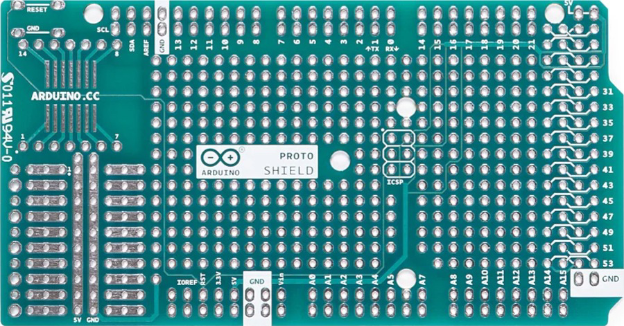
The Arduino Mega Proto Shield Rev3 (PCB) is a prototyping board designed specifically for the Arduino Mega. It allows users to create custom circuits and connect additional components with ease. The shield features a grid of soldering holes, enabling users to securely attach components and build permanent circuits. Additionally, it provides easy access to all the pins of the Arduino Mega, making it an ideal tool for prototyping and testing.
Explore Projects Built with Arduino Mega Proto Shield Rev3 (PCB)
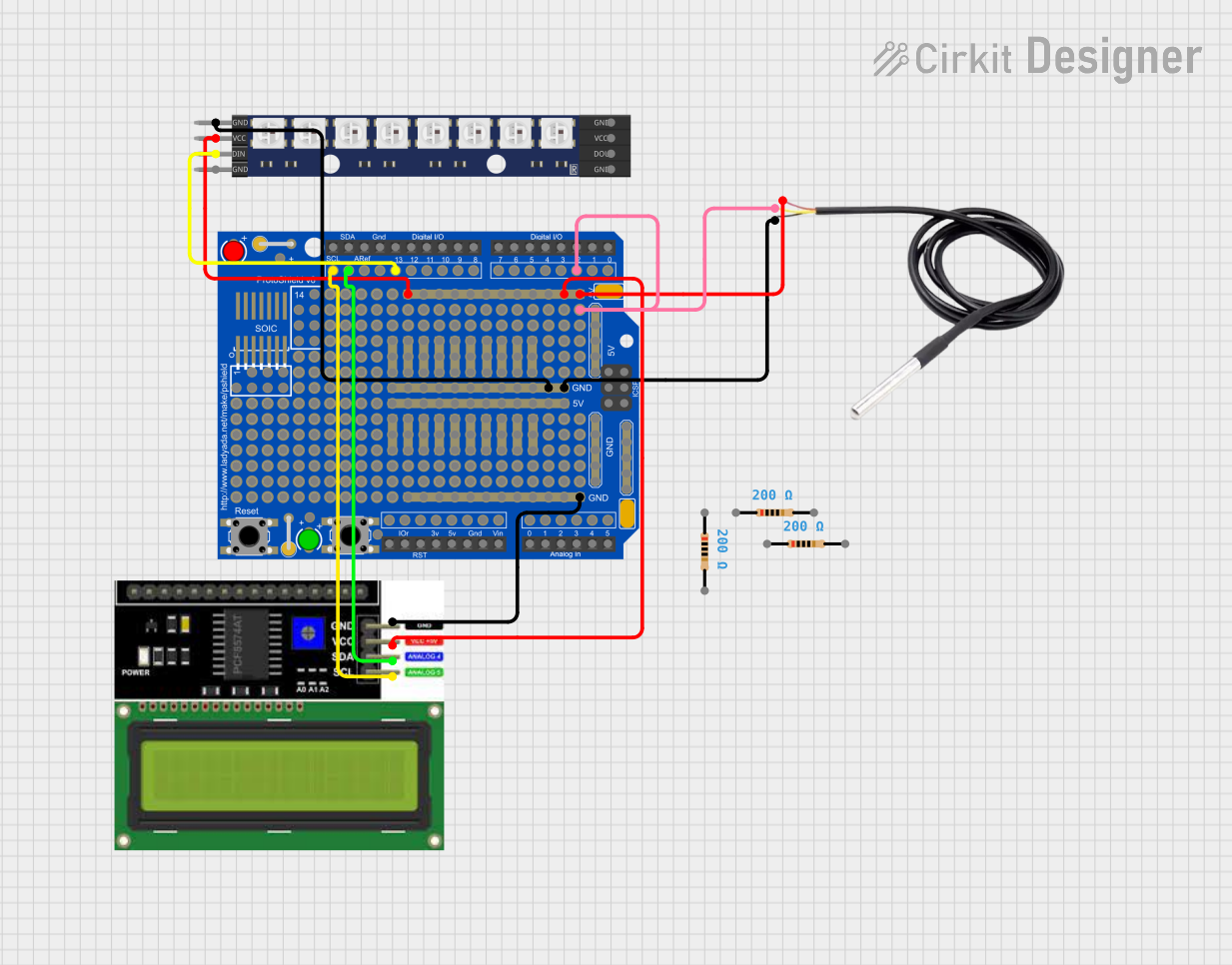

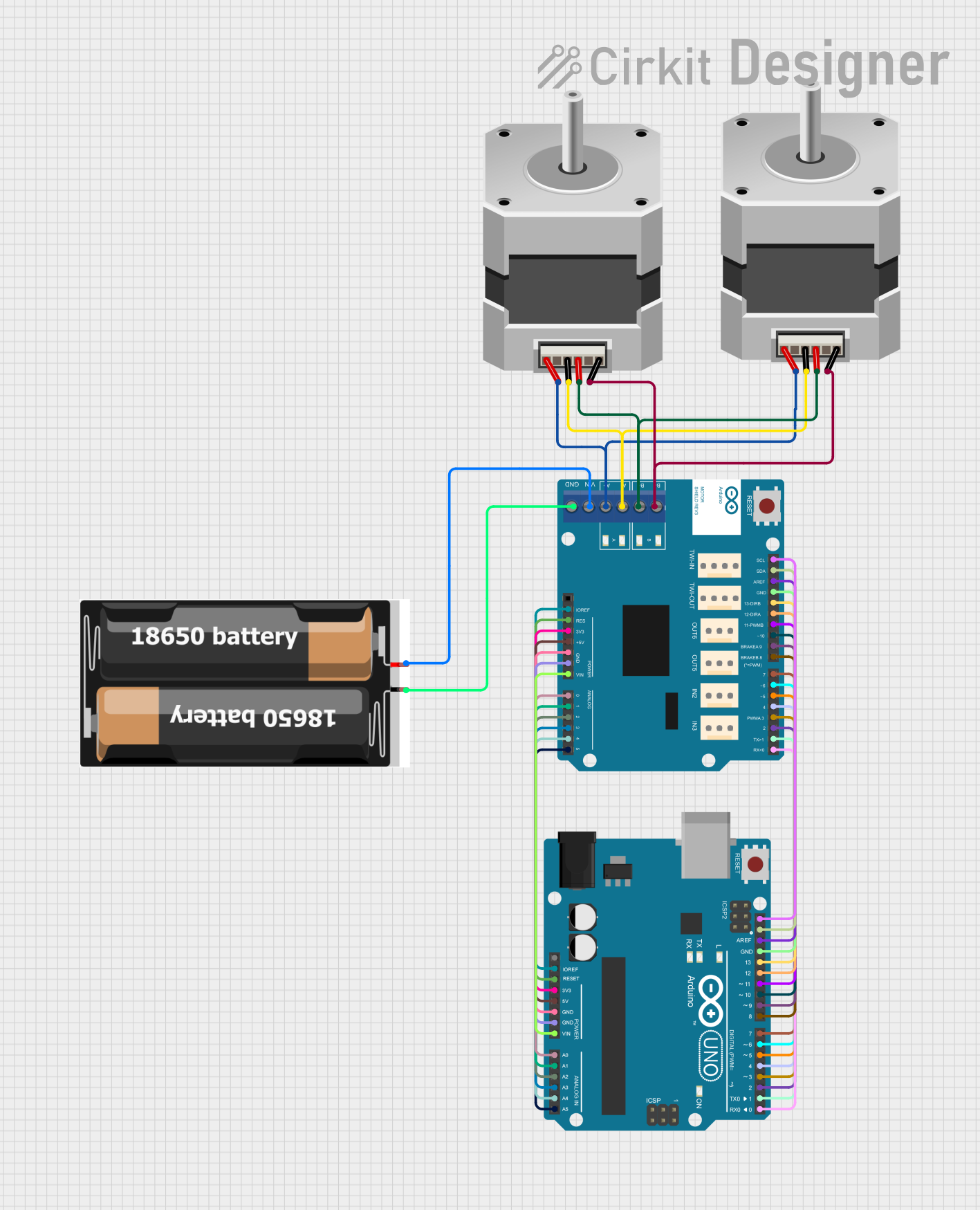
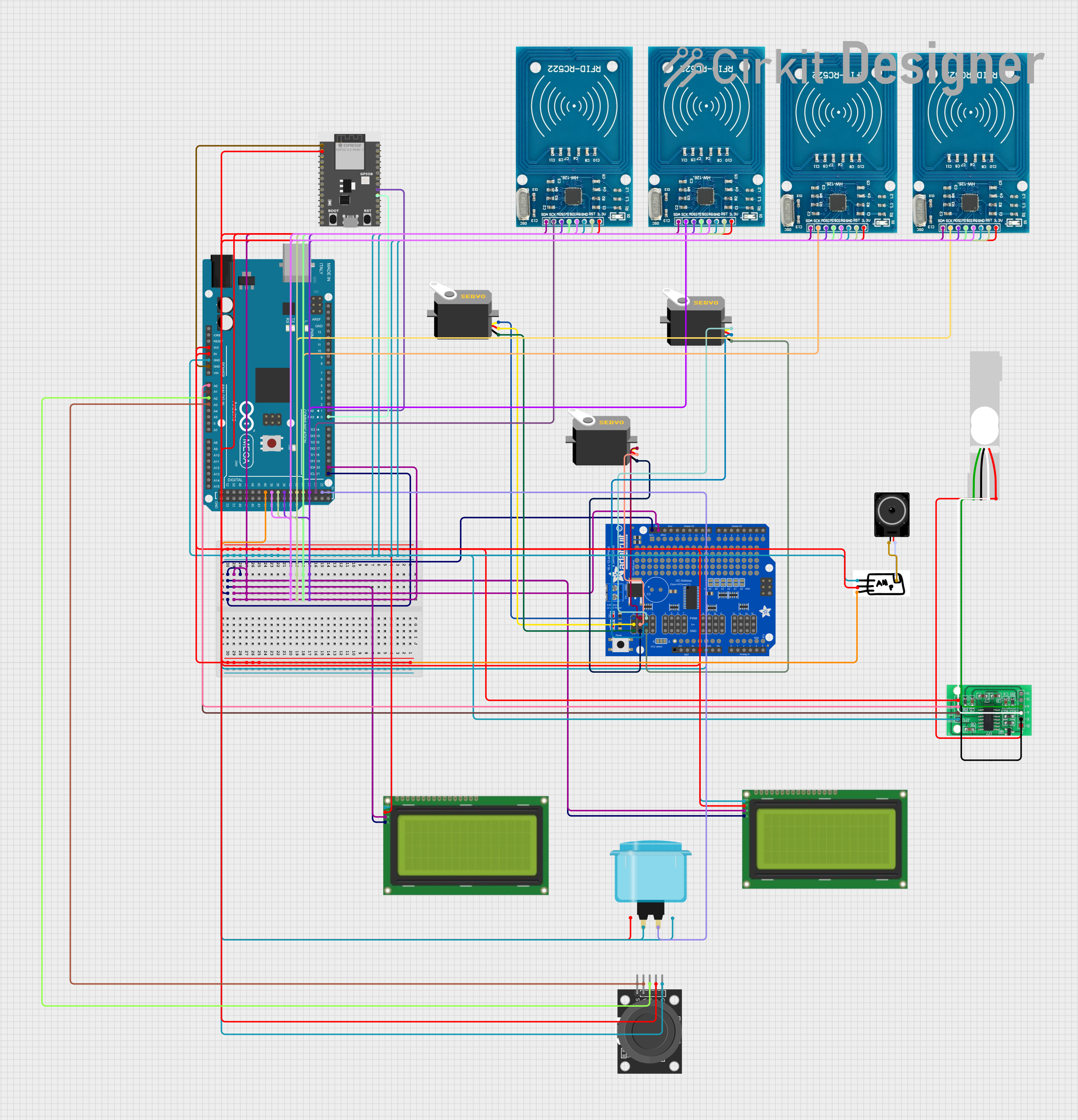
Explore Projects Built with Arduino Mega Proto Shield Rev3 (PCB)
Common Applications and Use Cases
- Building custom circuits for Arduino Mega projects
- Prototyping and testing new designs
- Creating permanent circuits for robotics, IoT, and automation projects
- Educational purposes for learning soldering and circuit design
Technical Specifications
Below are the key technical details of the Arduino Mega Proto Shield Rev3 (PCB):
| Specification | Details |
|---|---|
| Manufacturer | Arduino |
| Part ID | Arduino Mega Proto Shield Rev3 (PCB) |
| Compatibility | Arduino Mega and Arduino Mega 2560 |
| Dimensions | 101.5 mm x 53.3 mm |
| PCB Material | FR4 (Fiberglass Reinforced Epoxy Laminate) |
| Grid Hole Pitch | 2.54 mm (standard breadboard spacing) |
| Pin Headers | Female headers for all Arduino Mega pins |
| Additional Features | Reset button, ICSP header, and power rails for 5V and GND |
Pin Configuration and Descriptions
The Arduino Mega Proto Shield Rev3 (PCB) provides access to all the pins of the Arduino Mega. Below is a table summarizing the pin headers and their functions:
| Pin Header | Description |
|---|---|
| Digital Pins | Access to all 54 digital I/O pins of the Arduino Mega |
| Analog Pins | Access to all 16 analog input pins |
| Power Pins | Includes 5V, 3.3V, and GND connections |
| ICSP Header | Provides access to the In-Circuit Serial Programming (ICSP) interface |
| Reset Button | Allows manual resetting of the Arduino Mega |
Usage Instructions
How to Use the Arduino Mega Proto Shield Rev3 (PCB) in a Circuit
- Attach the Shield to the Arduino Mega: Align the shield's female headers with the Arduino Mega's male headers and gently press them together.
- Plan Your Circuit: Use the grid of holes to design your circuit. The holes are spaced at 2.54 mm, making it easy to solder standard components.
- Solder Components: Place your components on the grid and solder them securely. Use the power rails for 5V and GND connections.
- Connect External Components: Use jumper wires to connect external components to the shield's pin headers.
- Test Your Circuit: Upload your Arduino sketch to the Mega and test your circuit.
Important Considerations and Best Practices
- Avoid Overheating: When soldering, avoid overheating the PCB to prevent damage to the copper traces.
- Check Connections: Double-check all connections before powering the circuit to avoid short circuits.
- Use Proper Tools: Use a fine-tipped soldering iron and high-quality solder for precise and reliable connections.
- Label Your Circuit: If your circuit is complex, label the components and connections for easier debugging.
Example: Connecting an LED to the Shield
Below is an example of how to connect an LED to the Arduino Mega Proto Shield Rev3 (PCB) and control it using an Arduino sketch.
Circuit Setup
- Solder a 220-ohm resistor and an LED to the grid.
- Connect the resistor to digital pin 13 and the LED's cathode to GND.
Arduino Code
// Example code to blink an LED connected to pin 13 on the Arduino Mega Proto Shield

void setup() {
  pinMode(13, OUTPUT); // Set pin 13 as an output
}

void loop() {
  digitalWrite(13, HIGH); // Turn the LED on
  delay(1000);            // Wait for 1 second
  digitalWrite(13, LOW);  // Turn the LED off
  delay(1000);            // Wait for 1 second
}
Troubleshooting and FAQs
Common Issues and Solutions
Problem: The shield does not fit properly on the Arduino Mega.
- Solution: Ensure the shield's female headers are aligned with the Arduino Mega's male headers before pressing them together.
Problem: Components are not functioning as expected.
- Solution: Check all soldered connections for continuity and ensure there are no short circuits.
Problem: The Arduino Mega does not power on after attaching the shield.
- Solution: Verify that there are no short circuits on the shield and that the power rails are not overloaded.
Problem: The circuit behaves erratically.
- Solution: Ensure all components are properly grounded and that the power supply is stable.
FAQs
Q: Can I reuse the shield after soldering components?
A: Yes, but you will need to desolder the components carefully to avoid damaging the PCB.Q: Is the shield compatible with other Arduino boards?
A: No, the shield is specifically designed for the Arduino Mega and Mega 2560.Q: Can I use the shield without soldering?
A: While soldering is recommended for permanent circuits, you can use jumper wires for temporary connections.Q: Does the shield come with components?
A: No, the shield is a bare PCB and does not include any components. You will need to purchase components separately.
This concludes the documentation for the Arduino Mega Proto Shield Rev3 (PCB). Happy prototyping!