How to Use Battery AAx4 6V: Examples, Pinouts, and Specs
Introduction
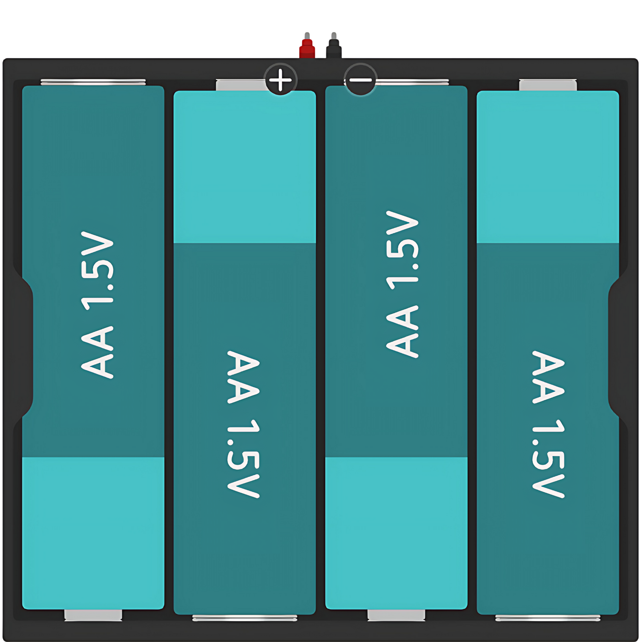
The Battery Holder for 4 AA Batteries (6V) is a simple and convenient way to power a wide range of electronic devices and projects. By housing four AA batteries, it provides a combined voltage output of 6V, which is suitable for many low-power applications. Common uses include powering small motors, LED lights, and portable electronic devices. It is also frequently used in DIY projects and educational electronics, such as robotics and Arduino-based circuits.
Explore Projects Built with Battery AAx4 6V

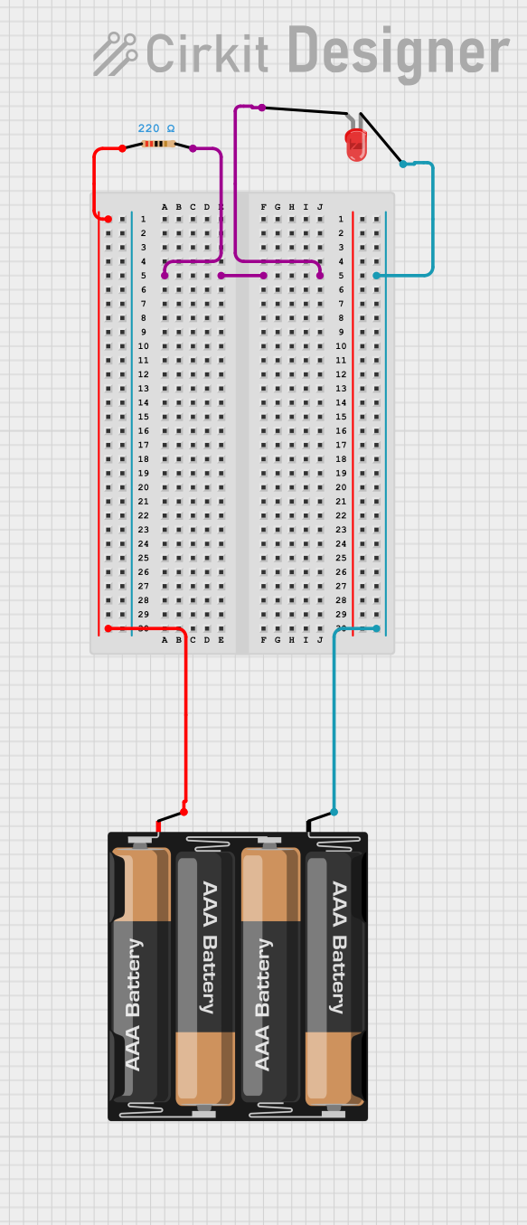
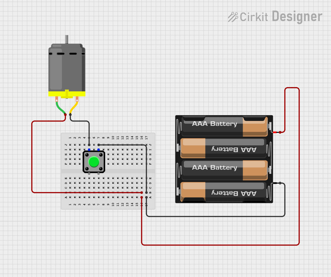
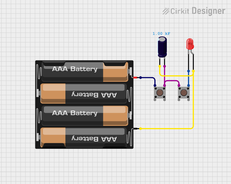
Explore Projects Built with Battery AAx4 6V
Technical Specifications
General Specifications
- Voltage Output: 6V (1.5V per AA battery)
- Battery Type: AA
- Number of Batteries: 4
- Material: Plastic
- Color: Often black or transparent
- Connector Type: Wires with or without a DC jack, or terminal leads
Pin Configuration and Descriptions
The battery holder typically has two leads: a positive lead (red wire) and a negative lead (black wire). Some models may include a DC barrel jack or other connectors.
| Pin | Color | Description |
|---|---|---|
| + | Red | Positive voltage output lead (connected to the positive terminal of the last battery in series) |
| - | Black | Negative voltage output lead (connected to the negative terminal of the first battery in series) |
Usage Instructions
Installing Batteries
- Open the battery holder, if it has a cover.
- Insert four AA batteries in accordance with the polarity markings inside the battery holder. Ensure that the positive (+) and negative (-) terminals match the markings.
- Close the battery holder securely.
Connecting to a Circuit
- Positive Lead (Red): Connect to the positive (+) power input of your device or circuit.
- Negative Lead (Black): Connect to the ground (GND) or negative (-) power input of your device or circuit.
Best Practices
- Always check the polarity before connecting the battery holder to your circuit to prevent damage.
- Remove batteries when the holder is not in use to prevent battery leakage and corrosion.
- Use batteries of the same type and brand for optimal performance and to prevent uneven discharge.
- Do not mix new and old batteries, as this can lead to leakage or reduced performance.
Troubleshooting and FAQs
Common Issues
- Device not powering on: Check the battery orientation and ensure that the connections are secure. Also, verify that the batteries are charged and functional.
- Intermittent power: Inspect the leads for any loose connections or damage. Ensure that the battery contacts are clean and making good contact with the batteries.
- Low power output: Replace old or depleted batteries with fresh ones. Ensure that all batteries are of the same type and charge level.
FAQs
Q: Can I use rechargeable AA batteries in this holder? A: Yes, rechargeable AA batteries can be used, but ensure they are all of the same type and charge level.
Q: What happens if I insert the batteries with incorrect polarity? A: Reversing the battery polarity can damage the electronic components in your circuit. Always double-check the polarity before use.
Q: Can I use this battery holder to power an Arduino UNO? A: Yes, an Arduino UNO can be powered with 6V, but it is recommended to use a voltage regulator to ensure a stable 5V supply.
Example Code for Arduino UNO
// This example demonstrates how to power an Arduino UNO using the 6V battery holder.
// No specific code is required to power the board; simply connect the battery holder.

void setup() {
  // Initialize digital pin LED_BUILTIN as an output.
  pinMode(LED_BUILTIN, OUTPUT);
}

void loop() {
  // Turn the LED on (HIGH is the voltage level)
  digitalWrite(LED_BUILTIN, HIGH);
  // Wait for a second
  delay(1000);
  // Turn the LED off by making the voltage LOW
  digitalWrite(LED_BUILTIN, LOW);
   // Wait for a second
  delay(1000);
}
Note: When using the battery holder to power an Arduino UNO, connect the positive lead to the Vin pin and the negative lead to one of the GND pins on the Arduino. Always ensure that the power does not exceed the recommended voltage for the board.