
How to Use LaNa WB: Examples, Pinouts, and Specs
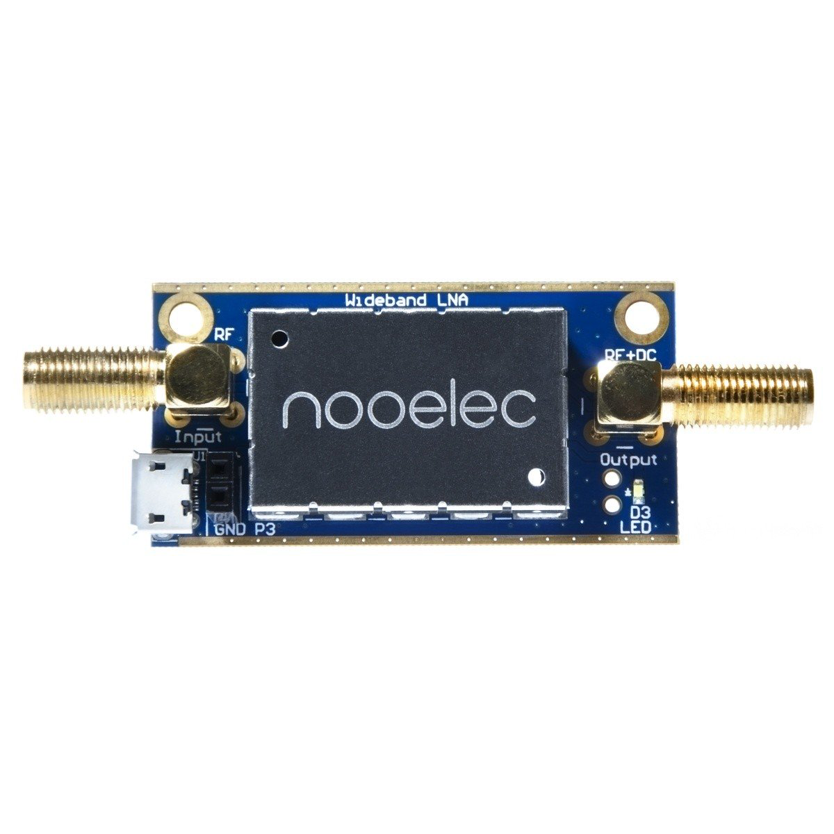
 Design with LaNa WB in Cirkit Designer
Introduction
The LaNa WB is a wideband amplifier manufactured by Nooelec (Part ID: lanawb). It is specifically designed for low noise and high gain applications, making it an ideal choice for RF and communication systems. The LaNa WB enhances signal strength across a broad frequency range, ensuring reliable performance in demanding environments.
Explore Projects Built with LaNa WB
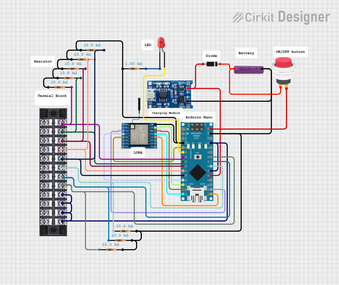 Open Project in Cirkit Designer
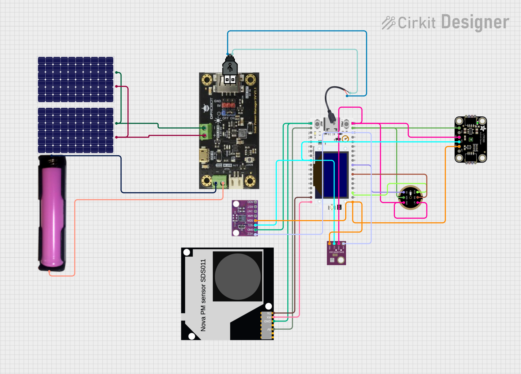 Open Project in Cirkit Designer
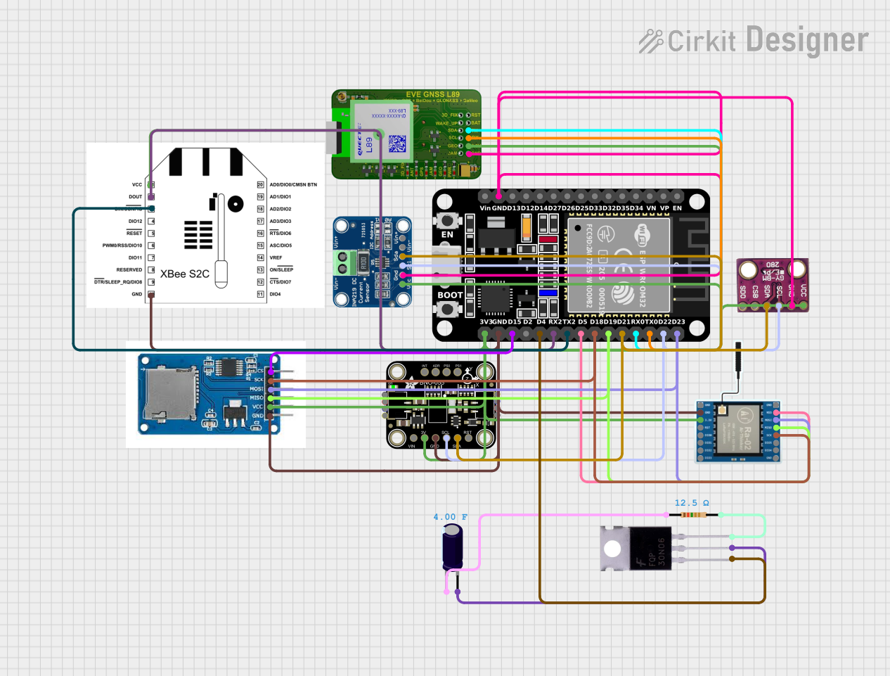 Open Project in Cirkit Designer
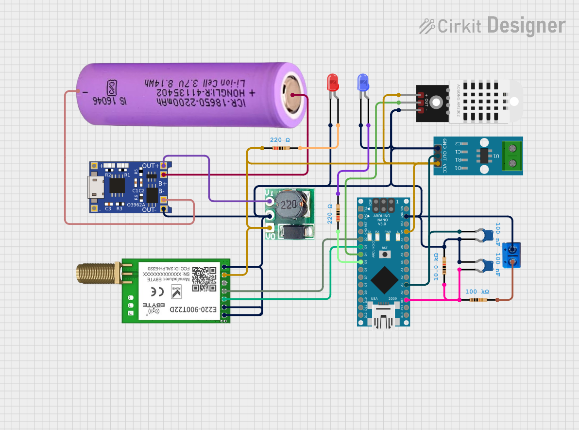 Open Project in Cirkit Designer
Explore Projects Built with LaNa WB
Open Project in Cirkit DesignerOpen Project in Cirkit DesignerOpen Project in Cirkit DesignerOpen Project in Cirkit DesignerCommon Applications and Use Cases
- RF signal amplification in communication systems
- Software-defined radio (SDR) setups
- Antenna signal boosting for weak signals
- Laboratory and research applications requiring low-noise amplification
- Amateur radio and satellite communication systems
Technical Specifications
Key Technical Details
| Parameter | Value |
|---|---|
| Frequency Range | 50 kHz to 3 GHz |
| Gain | 20 dB (typical) |
| Noise Figure | < 1 dB |
| Input Impedance | 50 Ω |
| Output Impedance | 50 Ω |
| Supply Voltage | 3.3V to 5V DC |
| Current Consumption | 50 mA (typical) |
| Connector Type | SMA Female (Input and Output) |
| Operating Temperature | -40°C to +85°C |
| Dimensions | 25 mm x 20 mm x 10 mm |
Pin Configuration and Descriptions
The LaNa WB uses SMA connectors for input and output signals and a 3-pin header for power supply. Below is the pin configuration:
| Pin Number | Pin Name | Description |
|---|---|---|
| 1 | VCC | Power supply input (3.3V to 5V DC) |
| 2 | GND | Ground connection |
| 3 | NC | Not connected (reserved for future use) |
Usage Instructions
How to Use the LaNa WB in a Circuit
- Power Supply: Connect the VCC pin to a stable DC power source (3.3V to 5V) and the GND pin to the ground of your circuit.
- Signal Input: Connect the RF signal source to the SMA input connector.
- Signal Output: Connect the SMA output connector to the next stage of your circuit (e.g., an SDR, antenna, or measurement device).
- Mounting: Secure the module on a non-conductive surface to avoid short circuits.
Important Considerations and Best Practices
- Power Supply: Ensure the power supply is clean and stable to avoid introducing noise into the amplified signal.
- Impedance Matching: Use 50 Ω cables and connectors to maintain proper impedance matching and minimize signal loss.
- Heat Dissipation: Although the LaNa WB operates efficiently, ensure adequate ventilation to prevent overheating during prolonged use.
- Signal Overload: Avoid input signals that exceed the module's maximum input power to prevent distortion or damage.
Example: Using LaNa WB with an Arduino UNO
The LaNa WB can be used in conjunction with an Arduino UNO for RF signal processing. Below is an example of how to power the LaNa WB using the Arduino's 5V pin:
Circuit Connection
- Connect the LaNa WB's VCC pin to the Arduino's 5V pin.
- Connect the LaNa WB's GND pin to the Arduino's GND pin.
- Connect the RF signal source and output as described above.
Arduino Code Example
Although the LaNa WB does not require direct programming, you can use the Arduino to monitor the power supply or control other components in the system. Here's an example:
// Example code to monitor the 5V power supply for the LaNa WB
// and ensure it remains within the acceptable range.

const int powerPin = A0; // Analog pin to monitor the 5V supply

void setup() {
  Serial.begin(9600); // Initialize serial communication
  pinMode(powerPin, INPUT); // Set the power pin as input
}

void loop() {
  int sensorValue = analogRead(powerPin); // Read the voltage level
  float voltage = sensorValue * (5.0 / 1023.0); // Convert to actual voltage

  // Print the voltage to the serial monitor
  Serial.print("Power Supply Voltage: ");
  Serial.print(voltage);
  Serial.println(" V");

  // Check if the voltage is within the acceptable range
  if (voltage < 3.3 || voltage > 5.0) {
    Serial.println("Warning: Voltage out of range!");
  }

  delay(1000); // Wait for 1 second before the next reading
}
Troubleshooting and FAQs
Common Issues and Solutions
| Issue | Possible Cause | Solution |
|---|---|---|
| No output signal | Incorrect power supply connection | Verify VCC and GND connections. |
| Distorted output signal | Input signal too strong | Reduce the input signal strength. |
| High noise in output signal | Poor power supply quality | Use a regulated and filtered power supply. |
| Overheating | Prolonged use without ventilation | Ensure proper airflow around the module. |
FAQs
Can the LaNa WB be used with a 12V power supply?
- No, the LaNa WB is designed to operate with a supply voltage between 3.3V and 5V. Using a higher voltage may damage the module.
What is the maximum input power the LaNa WB can handle?
- The LaNa WB can handle input signals up to 10 dBm without distortion.
Can I use the LaNa WB for frequencies below 50 kHz?
- The LaNa WB is optimized for frequencies between 50 kHz and 3 GHz. Performance below 50 kHz may not be reliable.
Is the LaNa WB suitable for outdoor use?
- The LaNa WB is not weatherproof. If used outdoors, it must be enclosed in a weather-resistant housing.
By following this documentation, users can effectively integrate the LaNa WB into their projects and troubleshoot common issues with ease.