How to Use abaisseur 220V AC to 24V DC: Examples, Pinouts, and Specs
Introduction
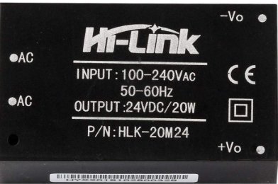
The HILINK 220V AC to 24V DC is a compact and efficient power supply module designed to convert high-voltage AC (220V) into a stable 24V DC output. This component is widely used in applications requiring low-voltage DC power, such as industrial control systems, IoT devices, LED lighting, and embedded systems. Its small size and high efficiency make it an excellent choice for space-constrained designs.
Explore Projects Built with abaisseur 220V AC to 24V DC


Explore Projects Built with abaisseur 220V AC to 24V DC
Common Applications
- Powering low-voltage DC devices from an AC mains supply
- Industrial automation and control systems
- LED drivers and lighting systems
- IoT devices and smart home applications
- Embedded systems and microcontroller-based projects
Technical Specifications
The following table outlines the key technical details of the HILINK 220V AC to 24V DC module:
| Parameter | Value |
|---|---|
| Input Voltage Range | 100V AC to 240V AC |
| Output Voltage | 24V DC |
| Output Current | 0.5A (maximum) |
| Output Power | 12W |
| Efficiency | ≥ 85% |
| Frequency Range | 50Hz to 60Hz |
| Operating Temperature | -25°C to +70°C |
| Storage Temperature | -40°C to +85°C |
| Dimensions | 52mm x 27mm x 22mm |
| Isolation Voltage | 3000V AC |
| Safety Standards | CE, RoHS compliant |
Pin Configuration and Descriptions
The module has six pins for input and output connections. The pin configuration is as follows:
| Pin Number | Pin Name | Description |
|---|---|---|
| 1 | AC-L | Live input for 220V AC |
| 2 | AC-N | Neutral input for 220V AC |
| 3 | GND | Ground for 24V DC output |
| 4 | +24V | Positive 24V DC output |
| 5 | NC | Not connected (leave unconnected) |
| 6 | NC | Not connected (leave unconnected) |
Usage Instructions
How to Use the Component in a Circuit
- Input Connection: Connect the AC-L and AC-N pins to the live and neutral wires of the 220V AC mains supply. Ensure proper insulation and safety precautions when handling high-voltage connections.
- Output Connection: Connect the GND and +24V pins to the load requiring 24V DC power. Verify the polarity to avoid damage to the connected device.
- Mounting: Secure the module in a well-ventilated area to prevent overheating. Avoid placing it near heat-sensitive components.
- Protection: Use a fuse or circuit breaker on the AC input side to protect against overcurrent or short circuits.
Important Considerations and Best Practices
- Safety First: Always disconnect the module from the mains supply before making any connections or modifications.
- Load Requirements: Ensure the connected load does not exceed the maximum output current of 0.5A.
- Heat Dissipation: Provide adequate ventilation or heat sinking if the module operates near its maximum power rating.
- Isolation: Maintain proper isolation between the high-voltage AC side and the low-voltage DC side to prevent electrical hazards.
Example: Using with an Arduino UNO
The HILINK 220V AC to 24V DC module can be used to power an Arduino UNO via a step-down regulator (e.g., LM2596) to convert 24V DC to 5V DC. Below is an example circuit and Arduino code:
Circuit Setup
- Connect the AC-L and AC-N pins to the 220V AC mains supply.
- Connect the +24V and GND pins to the input of an LM2596 step-down regulator.
- Set the LM2596 output to 5V DC and connect it to the Arduino UNO's 5V and GND pins.
Arduino Code Example
// Example code to blink an LED using Arduino UNO
// Ensure the HILINK module powers the Arduino via a step-down regulator

const int ledPin = 13; // Pin connected to the onboard LED

void setup() {
  pinMode(ledPin, OUTPUT); // Set the LED pin as an output
}

void loop() {
  digitalWrite(ledPin, HIGH); // Turn the LED on
  delay(1000);                // Wait for 1 second
  digitalWrite(ledPin, LOW);  // Turn the LED off
  delay(1000);                // Wait for 1 second
}
Troubleshooting and FAQs
Common Issues and Solutions
No Output Voltage
- Cause: Incorrect wiring or no AC input.
- Solution: Verify the AC-L and AC-N connections. Ensure the mains supply is active.
Overheating
- Cause: Operating near maximum load or poor ventilation.
- Solution: Reduce the load or improve ventilation around the module.
Output Voltage Fluctuations
- Cause: Unstable AC input or excessive load.
- Solution: Check the AC input voltage stability and ensure the load does not exceed 0.5A.
Module Not Powering On
- Cause: Blown fuse or damaged module.
- Solution: Replace the fuse or inspect the module for visible damage.
FAQs
Q1: Can this module be used with 110V AC input?
A1: Yes, the module supports an input voltage range of 100V AC to 240V AC.
Q2: Is the module suitable for outdoor use?
A2: No, the module is not weatherproof. Use it in a dry, indoor environment or within a weatherproof enclosure.
Q3: Can I connect multiple devices to the 24V output?
A3: Yes, as long as the total current draw does not exceed 0.5A.
Q4: Does the module require additional filtering?
A4: No, the module includes built-in filtering for stable DC output. However, additional filtering can be added if required for sensitive applications.