How to Use MDD20A Motor Driver: Examples, Pinouts, and Specs
Introduction
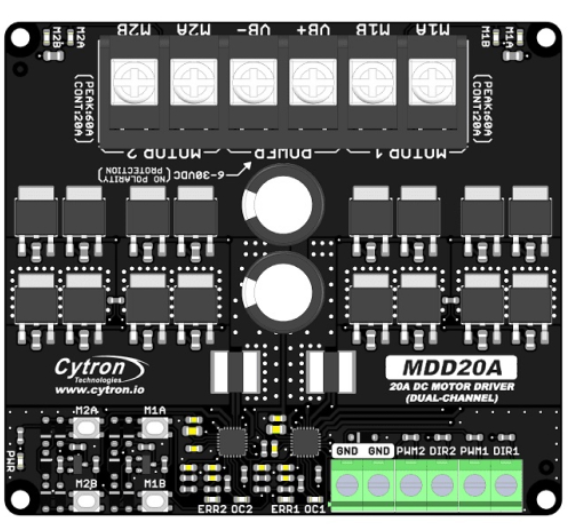
The MDD20A Motor Driver, manufactured by Cytron, is a robust dual-channel motor driver designed for controlling DC motors and stepper motors. It supports high current loads of up to 20A per channel continuously, making it suitable for demanding applications. The MDD20A offers features such as direction control, speed regulation via PWM (Pulse Width Modulation), and built-in protection mechanisms, ensuring reliable operation in robotics, automation, and industrial systems.
Explore Projects Built with MDD20A Motor Driver


Explore Projects Built with MDD20A Motor Driver
Common Applications
- Robotics (e.g., mobile robots, robotic arms)
- Conveyor belt systems
- Automated guided vehicles (AGVs)
- CNC machines and 3D printers
- Electric wheelchairs and mobility devices
Technical Specifications
The following table outlines the key technical details of the MDD20A Motor Driver:
| Parameter | Specification |
|---|---|
| Manufacturer | Cytron |
| Part ID | MDD20A |
| Channels | 2 (dual-channel) |
| Continuous Current | 20A per channel |
| Peak Current | 30A per channel (for 10 seconds) |
| Operating Voltage Range | 7V to 30V DC |
| Control Input Voltage | 3.3V or 5V logic compatible |
| PWM Frequency | Up to 20 kHz |
| Motor Type Supported | DC motors, stepper motors |
| Protection Features | Overcurrent, overtemperature, and reverse polarity |
| Dimensions | 84mm x 62mm x 25mm |
| Weight | 80g |
Pin Configuration and Descriptions
The MDD20A Motor Driver has a set of input and output pins for control and motor connections. The table below describes the pin configuration:
Input Pins
| Pin Name | Description |
|---|---|
| VIN | Power supply input (7V to 30V DC) |
| GND | Ground connection |
| AIN1 | Input signal for Motor A direction control |
| AIN2 | Input signal for Motor A direction control |
| PWMA | PWM input for Motor A speed control |
| BIN1 | Input signal for Motor B direction control |
| BIN2 | Input signal for Motor B direction control |
| PWMB | PWM input for Motor B speed control |
| ENA | Enable pin for Motor A (active HIGH) |
| ENB | Enable pin for Motor B (active HIGH) |
Output Pins
| Pin Name | Description |
|---|---|
| Motor A+ | Positive terminal for Motor A |
| Motor A- | Negative terminal for Motor A |
| Motor B+ | Positive terminal for Motor B |
| Motor B- | Negative terminal for Motor B |
Usage Instructions
How to Use the MDD20A in a Circuit
- Power Supply: Connect a DC power supply (7V to 30V) to the VIN and GND pins. Ensure the power supply can handle the current requirements of the motors.
- Motor Connections: Connect the DC motors or stepper motors to the Motor A+/- and Motor B+/- terminals.
- Control Signals: Use a microcontroller (e.g., Arduino UNO) to send control signals to the AIN1, AIN2, BIN1, BIN2, PWMA, and PWMB pins. These signals determine the direction and speed of the motors.
- Enable Pins: Set the ENA and ENB pins HIGH to enable Motor A and Motor B, respectively.
- PWM Control: Use PWM signals on the PWMA and PWMB pins to control motor speed. A higher duty cycle corresponds to a higher speed.
Important Considerations
- Heat Dissipation: The MDD20A can handle high currents, but it may generate heat during operation. Ensure proper ventilation or use a heatsink if necessary.
- Protection Features: The driver includes overcurrent, overtemperature, and reverse polarity protection. However, avoid exceeding the specified limits to ensure long-term reliability.
- Logic Level Compatibility: The control inputs are compatible with both 3.3V and 5V logic levels, making it suitable for a wide range of microcontrollers.
Example: Connecting the MDD20A to an Arduino UNO
Below is an example Arduino sketch to control two DC motors using the MDD20A:
// Define control pins for Motor A
const int AIN1 = 7;  // Direction control pin 1 for Motor A
const int AIN2 = 8;  // Direction control pin 2 for Motor A
const int PWMA = 9;  // PWM speed control pin for Motor A
const int ENA = 6;   // Enable pin for Motor A

// Define control pins for Motor B
const int BIN1 = 4;  // Direction control pin 1 for Motor B
const int BIN2 = 5;  // Direction control pin 2 for Motor B
const int PWMB = 3;  // PWM speed control pin for Motor B
const int ENB = 2;   // Enable pin for Motor B

void setup() {
  // Set all control pins as outputs
  pinMode(AIN1, OUTPUT);
  pinMode(AIN2, OUTPUT);
  pinMode(PWMA, OUTPUT);
  pinMode(ENA, OUTPUT);
  pinMode(BIN1, OUTPUT);
  pinMode(BIN2, OUTPUT);
  pinMode(PWMB, OUTPUT);
  pinMode(ENB, OUTPUT);

  // Enable both motors
  digitalWrite(ENA, HIGH);
  digitalWrite(ENB, HIGH);
}

void loop() {
  // Motor A: Forward at 50% speed
  digitalWrite(AIN1, HIGH);
  digitalWrite(AIN2, LOW);
  analogWrite(PWMA, 128);  // 50% duty cycle (128 out of 255)

  // Motor B: Reverse at 75% speed
  digitalWrite(BIN1, LOW);
  digitalWrite(BIN2, HIGH);
  analogWrite(PWMB, 192);  // 75% duty cycle (192 out of 255)

  delay(5000);  // Run for 5 seconds

  // Stop both motors
  analogWrite(PWMA, 0);
  analogWrite(PWMB, 0);

  delay(2000);  // Pause for 2 seconds
}
Troubleshooting and FAQs
Common Issues and Solutions
Motors Not Running
- Cause: ENA or ENB pins are not set HIGH.
- Solution: Ensure the enable pins are set HIGH in your code or circuit.
Overheating
- Cause: Prolonged operation at high currents without proper cooling.
- Solution: Add a heatsink or improve ventilation around the driver.
Erratic Motor Behavior
- Cause: Noise in the PWM signal or insufficient power supply.
- Solution: Use a stable power supply and ensure proper grounding.
Driver Not Responding
- Cause: Incorrect wiring or damaged components.
- Solution: Double-check all connections and verify the input voltage is within the specified range.
FAQs
Can the MDD20A control stepper motors? Yes, the MDD20A can control stepper motors by driving the coils with appropriate signals.
What is the maximum PWM frequency supported? The MDD20A supports PWM frequencies up to 20 kHz.
Is the MDD20A compatible with 3.3V microcontrollers? Yes, the control inputs are compatible with both 3.3V and 5V logic levels.
Does the MDD20A have built-in protection? Yes, it includes overcurrent, overtemperature, and reverse polarity protection.