How to Use Freenove ESP32-E 40pin: Examples, Pinouts, and Specs
Introduction
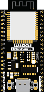
The Freenove ESP32-E 40pin is a versatile microcontroller board based on the powerful ESP32 chip. It features 40 pins for a wide range of input/output (I/O) connections, making it suitable for complex projects. With built-in Wi-Fi and Bluetooth capabilities, this board is ideal for Internet of Things (IoT) applications, smart devices, and embedded systems. Its compact design and robust performance make it a popular choice for both hobbyists and professionals.
Explore Projects Built with Freenove ESP32-E 40pin


Explore Projects Built with Freenove ESP32-E 40pin
Common Applications and Use Cases
- IoT devices and smart home automation
- Wireless sensor networks
- Robotics and control systems
- Data logging and remote monitoring
- Prototyping and educational projects
Technical Specifications
Below are the key technical details of the Freenove ESP32-E 40pin:
| Specification | Details |
|---|---|
| Microcontroller | ESP32 dual-core processor with Xtensa LX6 architecture |
| Clock Speed | Up to 240 MHz |
| Flash Memory | 4 MB |
| SRAM | 520 KB |
| Wi-Fi | IEEE 802.11 b/g/n |
| Bluetooth | Bluetooth 4.2 and BLE (Bluetooth Low Energy) |
| Operating Voltage | 3.3V |
| Input Voltage Range | 5V (via USB) or 7-12V (via VIN pin) |
| GPIO Pins | 34 (configurable as digital I/O, PWM, ADC, or DAC) |
| ADC Channels | 18 (12-bit resolution) |
| DAC Channels | 2 |
| Communication Interfaces | UART, SPI, I2C, I2S, CAN |
| Dimensions | 60mm x 25mm |
Pin Configuration and Descriptions
The Freenove ESP32-E 40pin has a total of 40 pins. Below is a table describing the key pins:
| Pin Name | Type | Description |
|---|---|---|
| VIN | Power Input | External power input (7-12V) |
| 3V3 | Power Output | 3.3V regulated output |
| GND | Ground | Ground connection |
| GPIO0 | Digital I/O | General-purpose I/O, also used for boot mode selection |
| GPIO2 | Digital I/O | General-purpose I/O |
| GPIO4 | Digital I/O | General-purpose I/O, supports PWM and ADC |
| GPIO12-15 | Digital I/O | General-purpose I/O, supports PWM, ADC, and SPI |
| GPIO34-39 | Input Only | Analog input pins (ADC only) |
| TXD0, RXD0 | UART | Default UART communication pins |
| SDA, SCL | I2C | I2C communication pins (default: GPIO21 for SDA, GPIO22 for SCL) |
| EN | Enable | Resets the chip when pulled low |
| BOOT | Boot Mode | Used to enter bootloader mode during programming |
Usage Instructions
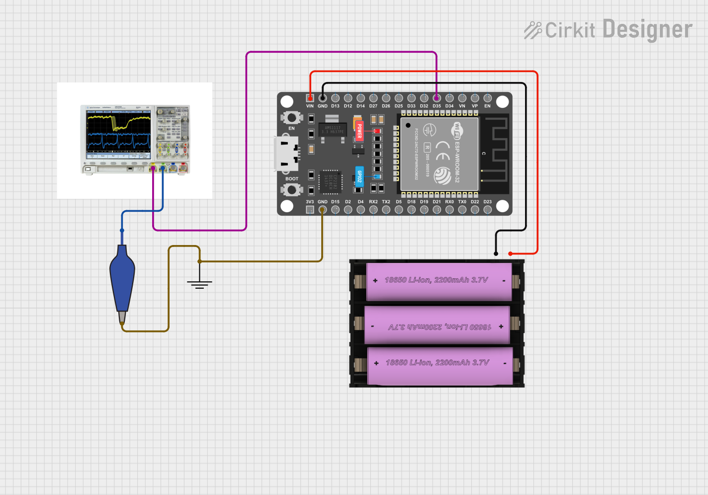
How to Use the Freenove ESP32-E 40pin in a Circuit
Powering the Board:
- Connect the board to a computer or USB power source using a micro-USB cable.
- Alternatively, supply 7-12V to the VIN pin for external power.
Programming the Board:
- Install the ESP32 board package in the Arduino IDE.
- Select the correct board (
ESP32 Dev Module) and port in the Arduino IDE. - Write or upload your code to the board via the USB connection.
Connecting Peripherals:
- Use the GPIO pins for connecting sensors, actuators, or other peripherals.
- Ensure that the voltage levels of connected devices are compatible with the 3.3V logic of the ESP32.
Using Wi-Fi and Bluetooth:
- Use the built-in libraries (
WiFi.handBluetoothSerial.h) to enable wireless communication.
- Use the built-in libraries (
Important Considerations and Best Practices
- Avoid supplying more than 3.3V to the GPIO pins to prevent damage to the board.
- Use level shifters if interfacing with 5V devices.
- Ensure proper grounding when connecting external components.
- Use decoupling capacitors for noise-sensitive applications.
- When using ADC pins, note that the input voltage range is 0-3.3V.
Example Code for Arduino IDE
Below is an example code to connect the Freenove ESP32-E 40pin to a Wi-Fi network and blink an LED:
#include <WiFi.h> // Include the Wi-Fi library

// Replace with your network credentials
const char* ssid = "Your_SSID";
const char* password = "Your_PASSWORD";

const int ledPin = 2; // GPIO2 is connected to the onboard LED

void setup() {
  pinMode(ledPin, OUTPUT); // Set GPIO2 as an output pin
  Serial.begin(115200);    // Start serial communication

  // Connect to Wi-Fi
  Serial.print("Connecting to Wi-Fi");
  WiFi.begin(ssid, password);
  while (WiFi.status() != WL_CONNECTED) {
    delay(500);
    Serial.print(".");
  }
  Serial.println("\nWi-Fi connected!");
  Serial.print("IP Address: ");
  Serial.println(WiFi.localIP());
}

void loop() {
  digitalWrite(ledPin, HIGH); // Turn the LED on
  delay(1000);                // Wait for 1 second
  digitalWrite(ledPin, LOW);  // Turn the LED off
  delay(1000);                // Wait for 1 second
}
Troubleshooting and FAQs
Common Issues and Solutions
The board is not detected by the computer:
- Ensure the USB cable is functional and supports data transfer.
- Install the correct USB-to-serial driver for the ESP32.
Wi-Fi connection fails:
- Double-check the SSID and password.
- Ensure the Wi-Fi network is within range.
GPIO pins not working as expected:
- Verify the pin mode configuration in your code.
- Check for conflicting pin assignments.
Board does not power on:
- Confirm the power source is within the recommended voltage range.
- Check for loose or faulty connections.
FAQs
Q: Can I use 5V sensors with the Freenove ESP32-E 40pin?
A: Yes, but you must use a level shifter to step down the voltage to 3.3V for the GPIO pins.
Q: How do I reset the board?
A: Press the EN (Enable) button to reset the board.
Q: Can I use the board with MicroPython?
A: Yes, the Freenove ESP32-E 40pin supports MicroPython. You can flash the MicroPython firmware to the board and use it for programming.
Q: What is the maximum current output of the 3.3V pin?
A: The 3.3V pin can supply a maximum current of approximately 500mA, depending on the input power source.
This concludes the documentation for the Freenove ESP32-E 40pin.