Cirkit Designer
Your all-in-one circuit design IDE
Home /
Component Documentation
How to Use 12V DC JGY370 Worm Motor: Examples, Pinouts, and Specs
Introduction
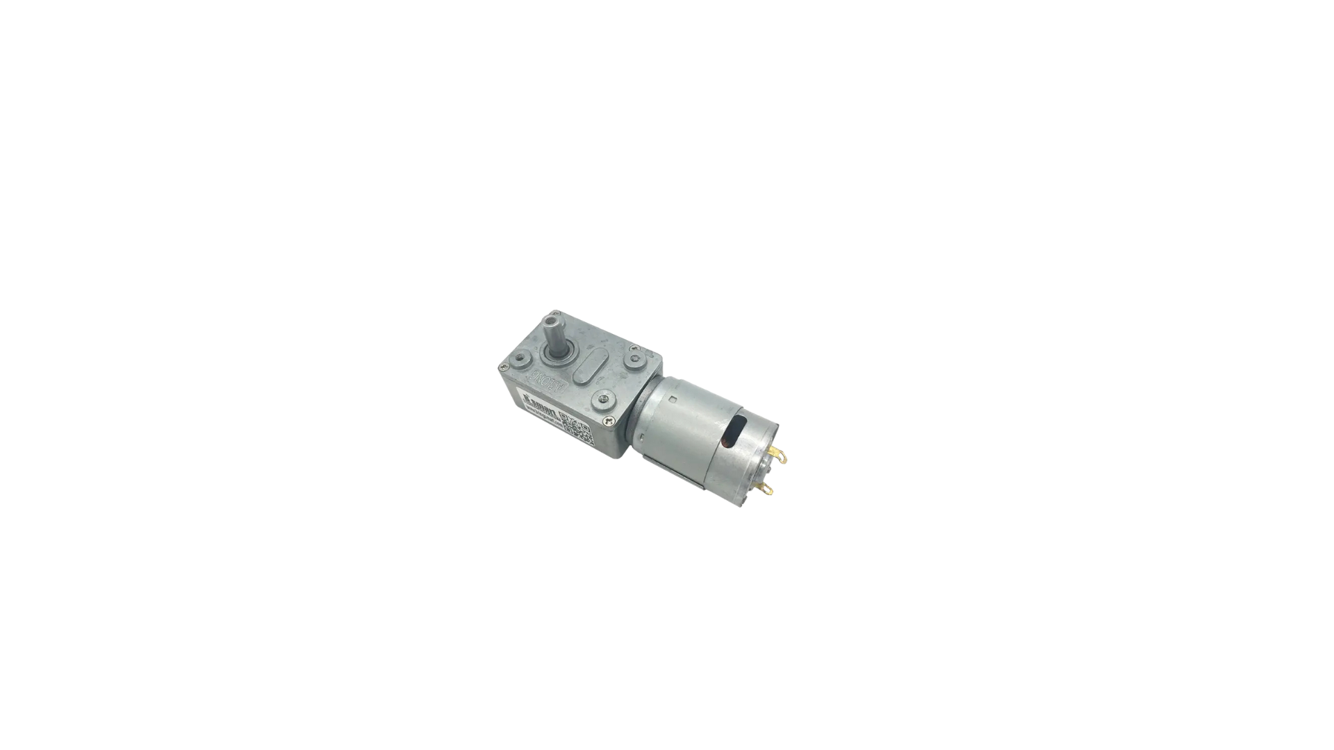
The 12V DC JGY370 Worm Motor by Synacorp is a robust and reliable motor designed for applications requiring high torque and low speed. This motor features a worm gear, which provides precise control and high power, making it ideal for various mechanical and robotic applications.
Explore Projects Built with 12V DC JGY370 Worm Motor
Arduino-Controlled Bluetooth Robotic Vehicle with Ultrasonic Navigation

This circuit is designed to remotely control two DC gearmotors using an Arduino UNO and an L298N motor driver, with an HC-05 Bluetooth module for wireless communication. It includes a JSN-SR04T ultrasonic sensor for distance measurement and a TM1637 display for output. Power management is handled by an 18650 Li-Ion battery and rocker switches.
PWM-Controlled DC Motor Speed Regulator with DC Barrel Jack Power Input

This circuit controls the speed of a DC motor using a 12V PWM speed controller. Power is supplied to the speed controller through a 2.1mm DC barrel jack, which then modulates the voltage and current to the motor's terminals to adjust its speed. There is no microcontroller code involved, indicating that the speed control is likely adjusted manually via the speed controller's onboard settings.
Battery-Powered DC Motor Control with LED Indicator
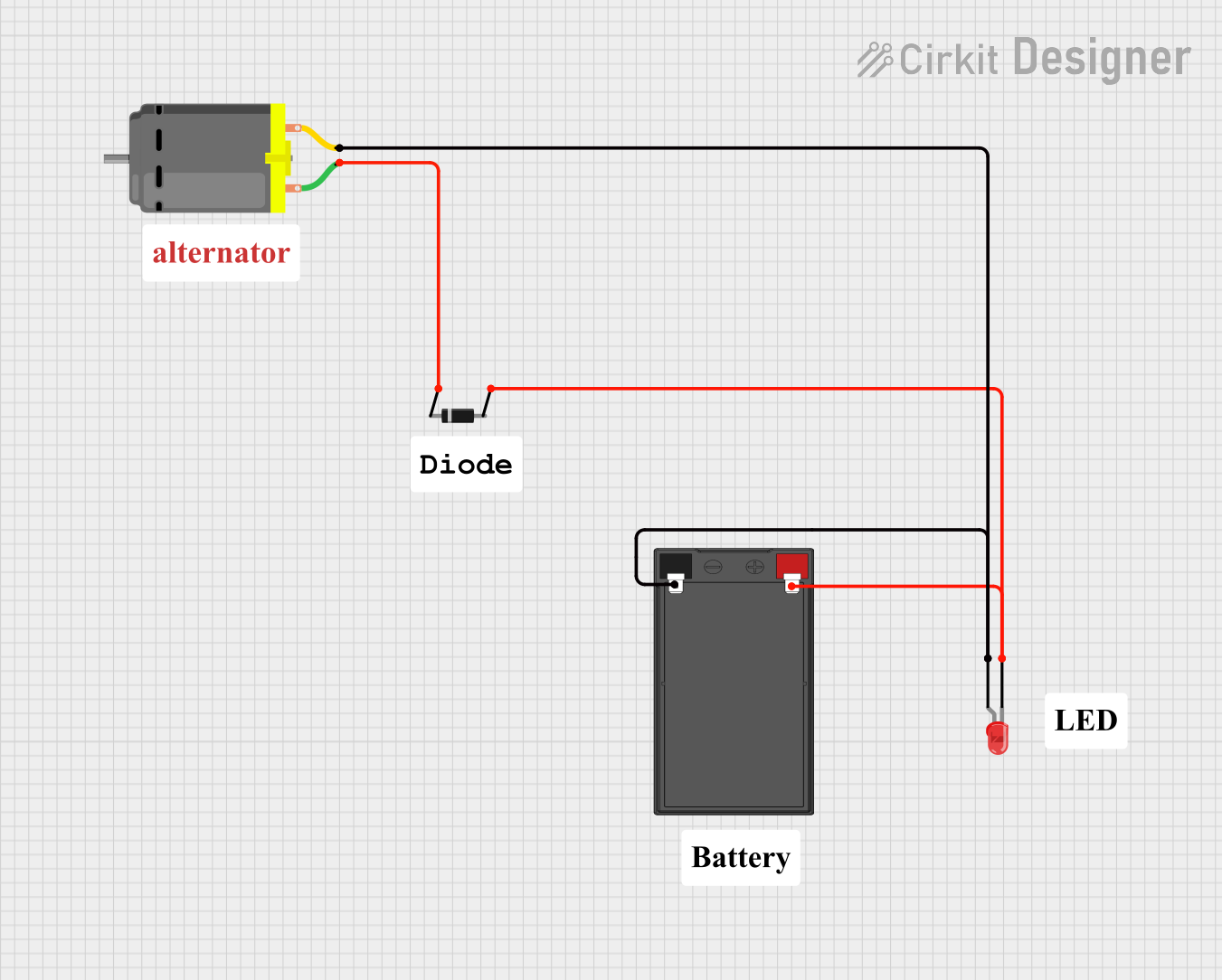
This circuit consists of a DC motor powered by a 12V battery, with a diode for protection against reverse voltage and an LED indicator. The LED is connected in parallel with the motor to indicate when the motor is powered.
Battery-Powered Motor Control Circuit with LED Indicators
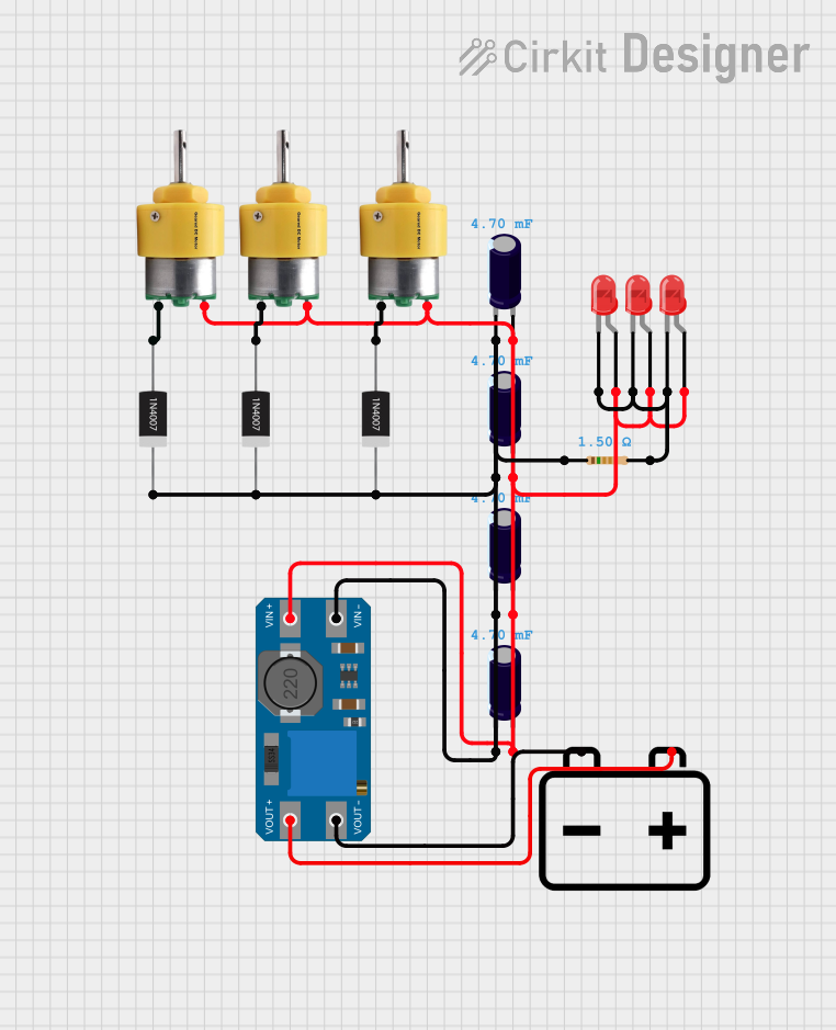
This circuit consists of three Center Shaft Metal Geared Motors, each protected by a 1N4007 Rectifier Diode, and powered by a 12V battery through an MT3608 boost converter. The circuit also includes multiple electrolytic capacitors for filtering and three red LEDs with a current-limiting resistor, indicating the operational status of the motors.
Explore Projects Built with 12V DC JGY370 Worm Motor
Arduino-Controlled Bluetooth Robotic Vehicle with Ultrasonic Navigation
This circuit is designed to remotely control two DC gearmotors using an Arduino UNO and an L298N motor driver, with an HC-05 Bluetooth module for wireless communication. It includes a JSN-SR04T ultrasonic sensor for distance measurement and a TM1637 display for output. Power management is handled by an 18650 Li-Ion battery and rocker switches.
PWM-Controlled DC Motor Speed Regulator with DC Barrel Jack Power Input
This circuit controls the speed of a DC motor using a 12V PWM speed controller. Power is supplied to the speed controller through a 2.1mm DC barrel jack, which then modulates the voltage and current to the motor's terminals to adjust its speed. There is no microcontroller code involved, indicating that the speed control is likely adjusted manually via the speed controller's onboard settings.
Battery-Powered DC Motor Control with LED Indicator
This circuit consists of a DC motor powered by a 12V battery, with a diode for protection against reverse voltage and an LED indicator. The LED is connected in parallel with the motor to indicate when the motor is powered.
Battery-Powered Motor Control Circuit with LED Indicators
This circuit consists of three Center Shaft Metal Geared Motors, each protected by a 1N4007 Rectifier Diode, and powered by a 12V battery through an MT3608 boost converter. The circuit also includes multiple electrolytic capacitors for filtering and three red LEDs with a current-limiting resistor, indicating the operational status of the motors.
Common Applications and Use Cases
- Robotics: Used for driving wheels, arms, and other moving parts.
- Automated Systems: Ideal for conveyor belts, automated gates, and other machinery.
- DIY Projects: Popular among hobbyists for custom-built machines and gadgets.
- Industrial Equipment: Suitable for applications requiring precise movement and high torque.
Technical Specifications
Key Technical Details
| Specification | Value |
|---|---|
| Manufacturer | Synacorp |
| Part ID | JGY370 |
| Operating Voltage | 12V DC |
| No-load Speed | 10-100 RPM (varies by model) |
| Rated Torque | 10-50 kg.cm (varies by model) |
| Gear Type | Worm Gear |
| Shaft Diameter | 6mm |
| Motor Dimensions | 70mm x 37mm x 30mm |
| Weight | 200g |
Pin Configuration and Descriptions
| Pin Number | Pin Name | Description |
|---|---|---|
| 1 | VCC | Power supply (12V DC) |
| 2 | GND | Ground |
| 3 | EN | Enable pin (optional, for control) |
| 4 | DIR | Direction control (optional) |
Usage Instructions
How to Use the Component in a Circuit
- Power Supply: Connect the VCC pin to a 12V DC power source and the GND pin to the ground.
- Control: If using an Arduino or other microcontroller, connect the EN and DIR pins to digital output pins for controlling the motor's speed and direction.
- Load Connection: Attach the motor shaft to the desired load, ensuring it is securely fastened.
Important Considerations and Best Practices
- Heat Dissipation: Ensure proper ventilation to prevent overheating during prolonged use.
- Power Supply: Use a stable 12V DC power source to avoid voltage fluctuations that could damage the motor.
- Load Matching: Match the motor's torque and speed specifications with the application's requirements to ensure optimal performance.
- Direction Control: Use the DIR pin to change the motor's direction. A HIGH signal typically indicates forward motion, while a LOW signal indicates reverse.
Example Circuit with Arduino UNO
// Example code to control the JGY370 Worm Motor with an Arduino UNO

const int enablePin = 9; // Pin connected to EN
const int dirPin = 8;    // Pin connected to DIR

void setup() {
  pinMode(enablePin, OUTPUT); // Set enable pin as output
  pinMode(dirPin, OUTPUT);    // Set direction pin as output
}

void loop() {
  digitalWrite(enablePin, HIGH); // Enable the motor
  digitalWrite(dirPin, HIGH);    // Set direction to forward
  delay(2000);                   // Run motor for 2 seconds

  digitalWrite(dirPin, LOW);     // Set direction to reverse
  delay(2000);                   // Run motor for 2 seconds

  digitalWrite(enablePin, LOW);  // Disable the motor
  delay(1000);                   // Wait for 1 second
}
Troubleshooting and FAQs
Common Issues Users Might Face
Motor Not Running:
- Solution: Check the power supply connections and ensure the voltage is 12V DC. Verify that the EN pin is set to HIGH.
Motor Overheating:
- Solution: Ensure proper ventilation and avoid running the motor at maximum load for extended periods.
Inconsistent Speed:
- Solution: Use a stable power supply and check for any mechanical obstructions in the load.
Direction Control Not Working:
- Solution: Verify the connections to the DIR pin and ensure the control signals are correctly set.
Solutions and Tips for Troubleshooting
- Check Connections: Ensure all connections are secure and correctly oriented.
- Use Proper Power Supply: A regulated 12V DC power supply is recommended for consistent performance.
- Monitor Temperature: Regularly check the motor's temperature during operation to prevent overheating.
- Consult Datasheet: Refer to the manufacturer's datasheet for detailed specifications and guidelines.
By following this documentation, users can effectively utilize the 12V DC JGY370 Worm Motor in their projects, ensuring reliable performance and longevity.