
How to Use PIR motion sensor: Examples, Pinouts, and Specs
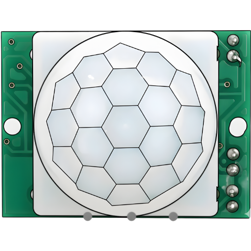
 Design with PIR motion sensor in Cirkit Designer
Introduction
A Passive Infrared (PIR) motion sensor detects motion by measuring changes in infrared radiation, typically emitted by warm bodies such as humans or animals. These sensors are widely used in applications where motion detection is required, such as security systems, automatic lighting, and energy-saving devices. PIR sensors are cost-effective, reliable, and easy to integrate into various electronic systems.
Explore Projects Built with PIR motion sensor
 Open Project in Cirkit Designer
 Open Project in Cirkit Designer
 Open Project in Cirkit Designer
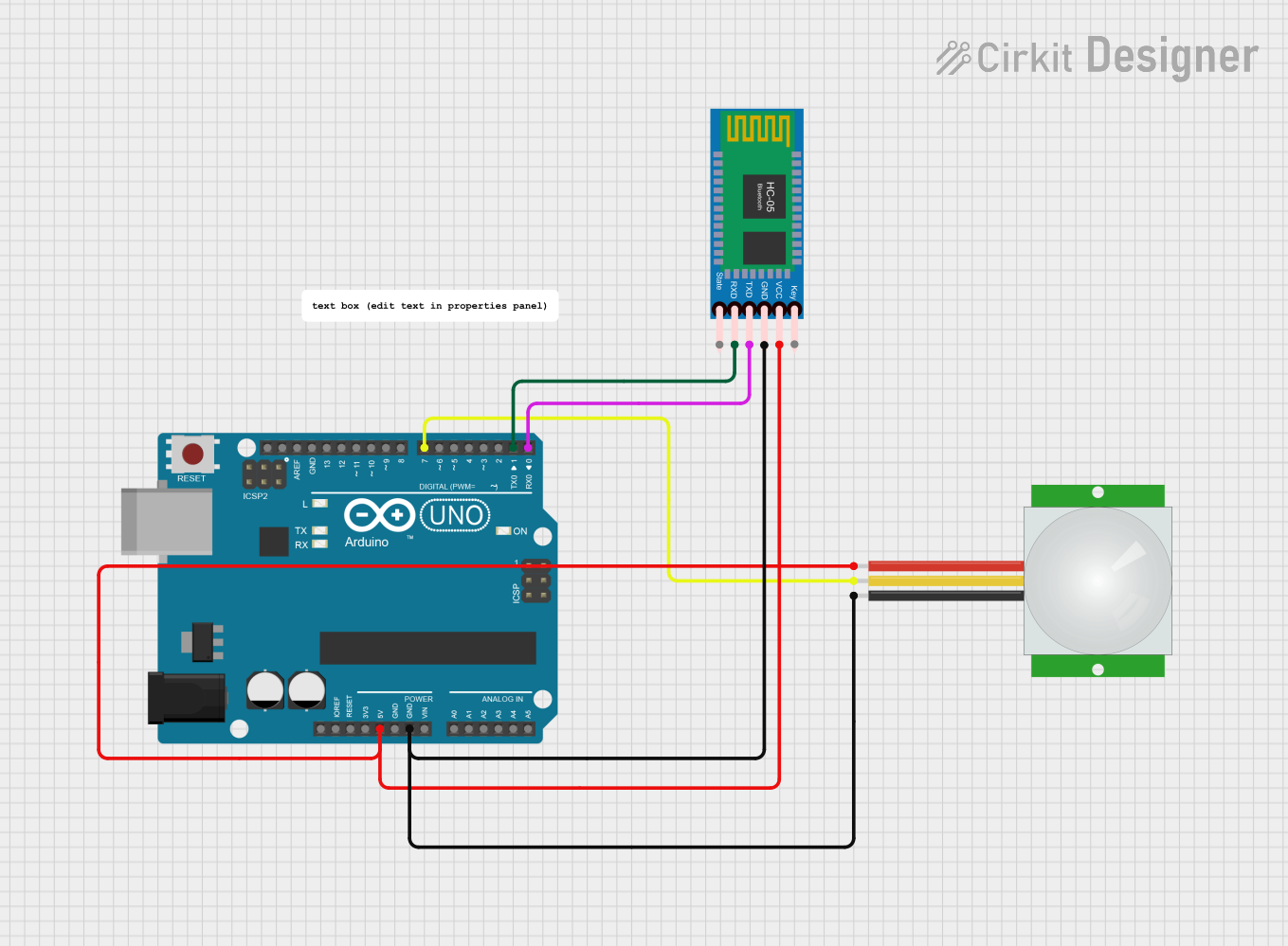 Open Project in Cirkit Designer
Explore Projects Built with PIR motion sensor
Open Project in Cirkit DesignerOpen Project in Cirkit DesignerOpen Project in Cirkit DesignerOpen Project in Cirkit DesignerTechnical Specifications
Below are the key technical details of a typical PIR motion sensor:
| Parameter | Value |
|---|---|
| Operating Voltage | 3.3V to 5V |
| Current Consumption | < 60 µA (standby), ~1 mA (active) |
| Detection Range | 3 to 7 meters (adjustable) |
| Detection Angle | ~120° |
| Output Signal | Digital (High/Low) |
| Trigger Modes | Repeatable (H) / Non-repeatable (L) |
| Warm-up Time | ~30 seconds |
| Operating Temperature | -20°C to 50°C |
Pin Configuration and Descriptions
The PIR motion sensor typically has three pins:
| Pin | Name | Description |
|---|---|---|
| 1 | VCC | Power supply pin. Connect to 3.3V or 5V depending on the sensor's specifications. |
| 2 | OUT | Digital output pin. Outputs HIGH when motion is detected, LOW otherwise. |
| 3 | GND | Ground pin. Connect to the ground of the circuit. |
Usage Instructions
How to Use the PIR Motion Sensor in a Circuit
- Power the Sensor: Connect the VCC pin to a 3.3V or 5V power source and the GND pin to the ground.
- Connect the Output: Connect the OUT pin to a microcontroller's digital input pin or directly to an external device (e.g., an LED or buzzer) through a resistor.
- Adjust Sensitivity and Delay: Use the onboard potentiometers to adjust the detection range (sensitivity) and the delay time for the output signal.
- Warm-up Period: Allow the sensor to stabilize for approximately 30 seconds after powering it on.
Important Considerations and Best Practices
- Avoid Direct Sunlight: Place the sensor away from direct sunlight or heat sources to prevent false triggers.
- Stable Power Supply: Ensure a stable power supply to avoid erratic behavior.
- Mounting Position: Install the sensor at an appropriate height and angle for optimal coverage.
- Trigger Modes: Set the trigger mode (repeatable or non-repeatable) using the onboard jumper or switch:
- Repeatable (H): The output remains HIGH as long as motion is detected.
- Non-repeatable (L): The output goes HIGH for a set delay time, even if motion continues.
Example: Connecting to an Arduino UNO
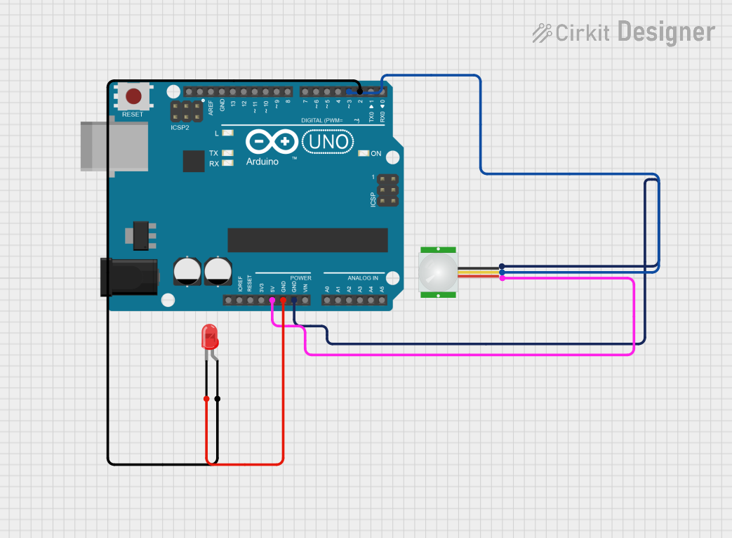
Below is an example of how to connect and use a PIR motion sensor with an Arduino UNO:
Circuit Connections
- VCC: Connect to the Arduino's 5V pin.
- GND: Connect to the Arduino's GND pin.
- OUT: Connect to digital pin 2 on the Arduino.
Arduino Code
// PIR Motion Sensor Example with Arduino UNO
// This code reads the PIR sensor's output and turns on an LED when motion is detected.

#define PIR_PIN 2       // Define the pin connected to the PIR sensor's OUT pin
#define LED_PIN 13      // Define the pin connected to the onboard LED

void setup() {
  pinMode(PIR_PIN, INPUT);  // Set PIR_PIN as an input
  pinMode(LED_PIN, OUTPUT); // Set LED_PIN as an output
  Serial.begin(9600);       // Initialize serial communication for debugging
}

void loop() {
  int motionDetected = digitalRead(PIR_PIN); // Read the PIR sensor's output

  if (motionDetected == HIGH) { // If motion is detected
    digitalWrite(LED_PIN, HIGH); // Turn on the LED
    Serial.println("Motion detected!"); // Print message to serial monitor
  } else {
    digitalWrite(LED_PIN, LOW);  // Turn off the LED
    Serial.println("No motion."); // Print message to serial monitor
  }

  delay(100); // Small delay to stabilize readings
}
Troubleshooting and FAQs
Common Issues and Solutions
False Triggers:
- Cause: Heat sources, sunlight, or electrical noise.
- Solution: Relocate the sensor, shield it from heat sources, or use decoupling capacitors on the power supply.
No Detection:
- Cause: Incorrect wiring or insufficient warm-up time.
- Solution: Double-check connections and wait for the sensor to stabilize after powering on.
Unstable Output:
- Cause: Unstable power supply or interference.
- Solution: Use a regulated power supply and keep the sensor away from high-frequency devices.
FAQs
Q1: Can the detection range be increased?
A1: Yes, the detection range can be adjusted using the onboard sensitivity potentiometer. However, increasing the range may also increase the likelihood of false triggers.
Q2: How long does the sensor stay HIGH after detecting motion?
A2: The delay time is adjustable using the onboard delay potentiometer. It typically ranges from a few seconds to several minutes.
Q3: Can the PIR sensor detect motion through glass?
A3: No, PIR sensors cannot detect motion through glass as infrared radiation does not pass through it effectively.
Q4: Is the PIR sensor waterproof?
A4: Most PIR sensors are not waterproof. If outdoor use is required, ensure the sensor is housed in a weatherproof enclosure.