Cirkit Designer Logo
Cirkit Designer
Your all-in-one circuit design IDE
Home / 
Component Documentation

How to Use TS832 TRANSMITTER: Examples, Pinouts, and Specs

Image of TS832 TRANSMITTER
Cirkit Designer LogoDesign with TS832 TRANSMITTER in Cirkit Designer

Introduction

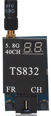
The TS832 Transmitter by AKK (Part ID: VTX) is a 5.8GHz wireless video transmitter designed for long-distance video signal transmission. It is widely used in First Person View (FPV) applications, such as drones, RC vehicles, and other remote-controlled systems. The TS832 provides a reliable, high-quality video transmission with adjustable power output and multiple selectable channels, ensuring minimal interference and optimal performance.

Explore Projects Built with TS832 TRANSMITTER

Use Cirkit Designer to design, explore, and prototype these projects online. Some projects support real-time simulation. Click "Open Project" to start designing instantly!
ESP32-Based RF Communication System with 433 MHz Modules
Image of 433 mhz: A project utilizing TS832 TRANSMITTER in a practical application
This circuit comprises an ESP32 microcontroller connected to a 433 MHz RF transmitter and receiver pair. The ESP32 is programmed to receive and decode RF signals through the receiver module, as well as send RF signals via the transmitter module. Additionally, the ESP32 can communicate with a Bluetooth device to exchange commands and data, and it uses an LED for status indication.
Cirkit Designer LogoOpen Project in Cirkit Designer
Satellite-Based Timing and Navigation System with SDR and Atomic Clock Synchronization
Image of GPS 시스템 측정 구성도_Confirm: A project utilizing TS832 TRANSMITTER in a practical application
This circuit appears to be a complex system involving power supply management, GPS and timing synchronization, and data communication. It includes a SI-TEX G1 Satellite Compass for GPS data, an XHTF1021 Atomic Rubidium Clock for precise timing, and Ettus USRP B200 units for software-defined radio communication. Power is supplied through various SMPS units and distributed via terminal blocks and DC jacks. Data communication is facilitated by Beelink MINI S12 N95 computers, RS232 splitters, and a 1000BASE-T Media Converter for network connectivity. RF Directional Couplers are used to interface antennas with the USRP units, and the entire system is likely contained within cases for protection and organization.
Cirkit Designer LogoOpen Project in Cirkit Designer
Configurable Battery-Powered RF Signal Transmitter with DIP Switch Settings
Image of fyp transmitter: A project utilizing TS832 TRANSMITTER in a practical application
This circuit appears to be a configurable encoder system with an RF transmission capability. The encoder's address pins (A0-A7) are connected to a DIP switch for setting the address, and its data output (DO) is connected to an RF transmitter, allowing the encoded signal to be wirelessly transmitted. The circuit is powered by a 9V battery, regulated to 5V by a 7805 voltage regulator, and includes a diode for polarity protection. Tactile switches are connected to the encoder's data inputs (D1-D3), and an LED with a current-limiting resistor indicates power or activity.
Cirkit Designer LogoOpen Project in Cirkit Designer
Battery-Powered nRF52840 and HT-RA62 Communication Module
Image of NRF52840+HT-RA62: A project utilizing TS832 TRANSMITTER in a practical application
This circuit is a wireless communication system powered by a 18650 Li-ion battery, featuring an nRF52840 ProMicro microcontroller and an HT-RA62 transceiver module. The nRF52840 handles the control logic and interfaces with the HT-RA62 for data transmission, while the battery provides the necessary power for the entire setup.
Cirkit Designer LogoOpen Project in Cirkit Designer

Explore Projects Built with TS832 TRANSMITTER

Use Cirkit Designer to design, explore, and prototype these projects online. Some projects support real-time simulation. Click "Open Project" to start designing instantly!
Image of 433 mhz: A project utilizing TS832 TRANSMITTER in a practical application
ESP32-Based RF Communication System with 433 MHz Modules
This circuit comprises an ESP32 microcontroller connected to a 433 MHz RF transmitter and receiver pair. The ESP32 is programmed to receive and decode RF signals through the receiver module, as well as send RF signals via the transmitter module. Additionally, the ESP32 can communicate with a Bluetooth device to exchange commands and data, and it uses an LED for status indication.
Cirkit Designer LogoOpen Project in Cirkit Designer
Image of GPS 시스템 측정 구성도_Confirm: A project utilizing TS832 TRANSMITTER in a practical application
Satellite-Based Timing and Navigation System with SDR and Atomic Clock Synchronization
This circuit appears to be a complex system involving power supply management, GPS and timing synchronization, and data communication. It includes a SI-TEX G1 Satellite Compass for GPS data, an XHTF1021 Atomic Rubidium Clock for precise timing, and Ettus USRP B200 units for software-defined radio communication. Power is supplied through various SMPS units and distributed via terminal blocks and DC jacks. Data communication is facilitated by Beelink MINI S12 N95 computers, RS232 splitters, and a 1000BASE-T Media Converter for network connectivity. RF Directional Couplers are used to interface antennas with the USRP units, and the entire system is likely contained within cases for protection and organization.
Cirkit Designer LogoOpen Project in Cirkit Designer
Image of fyp transmitter: A project utilizing TS832 TRANSMITTER in a practical application
Configurable Battery-Powered RF Signal Transmitter with DIP Switch Settings
This circuit appears to be a configurable encoder system with an RF transmission capability. The encoder's address pins (A0-A7) are connected to a DIP switch for setting the address, and its data output (DO) is connected to an RF transmitter, allowing the encoded signal to be wirelessly transmitted. The circuit is powered by a 9V battery, regulated to 5V by a 7805 voltage regulator, and includes a diode for polarity protection. Tactile switches are connected to the encoder's data inputs (D1-D3), and an LED with a current-limiting resistor indicates power or activity.
Cirkit Designer LogoOpen Project in Cirkit Designer
Image of NRF52840+HT-RA62: A project utilizing TS832 TRANSMITTER in a practical application
Battery-Powered nRF52840 and HT-RA62 Communication Module
This circuit is a wireless communication system powered by a 18650 Li-ion battery, featuring an nRF52840 ProMicro microcontroller and an HT-RA62 transceiver module. The nRF52840 handles the control logic and interfaces with the HT-RA62 for data transmission, while the battery provides the necessary power for the entire setup.
Cirkit Designer LogoOpen Project in Cirkit Designer

Common Applications

  • FPV drones and quadcopters
  • Remote-controlled cars and boats
  • Wireless video surveillance systems
  • Robotics and unmanned vehicles
  • Long-range video transmission for hobbyists and professionals

Technical Specifications

Key Technical Details

Parameter Specification
Operating Frequency 5.8GHz
Channels 40 selectable channels
Output Power Adjustable: 600mW
Input Voltage 7V - 24V DC
Current Consumption 220mA at 12V
Video Input Format NTSC/PAL
Antenna Connector RP-SMA Male
Dimensions 54mm x 32mm x 10mm
Weight 21g
Operating Temperature -10°C to 85°C
Transmission Range Up to 5km (line of sight, with proper antenna)

Pin Configuration and Descriptions

The TS832 Transmitter has a 5-pin connector for power and video input. Below is the pinout:

Pin Number Label Description
1 GND Ground connection
2 +V IN Power input (7V - 24V DC)
3 VIDEO IN Composite video input
4 AUDIO IN L Left audio channel input
5 AUDIO IN R Right audio channel input

Usage Instructions

How to Use the TS832 in a Circuit

  1. Power Supply: Connect the +V IN pin to a DC power source (7V - 24V) and the GND pin to ground. Ensure the power source can supply at least 220mA at 12V.
  2. Video Input: Connect the VIDEO IN pin to the composite video output of your camera or video source.
  3. Audio Input (Optional): If audio transmission is required, connect the AUDIO IN L and AUDIO IN R pins to the left and right audio outputs of your source.
  4. Antenna: Attach a 5.8GHz antenna to the RP-SMA connector. Use a high-gain antenna for extended range.
  5. Channel Selection: Use the DIP switches on the transmitter to select the desired frequency channel. Refer to the channel table in the TS832 datasheet for switch settings.

Important Considerations and Best Practices

  • Cooling: The TS832 can become hot during operation. Ensure proper ventilation or use a heat sink to prevent overheating.
  • Antenna Connection: Always connect the antenna before powering on the transmitter to avoid damage to the RF circuitry.
  • Frequency Selection: Choose a channel that minimizes interference with other devices operating in the 5.8GHz band.
  • Power Regulation: Use a stable power supply to avoid voltage fluctuations that could affect performance.

Example: Connecting TS832 to an Arduino UNO

While the TS832 is not directly controlled by an Arduino, you can use an Arduino to switch the transmitter on/off or control peripherals like cameras. Below is an example of using an Arduino to toggle the TS832 power via a relay:

// Example: Controlling TS832 power with Arduino and a relay module

const int relayPin = 7; // Pin connected to the relay module

void setup() {
  pinMode(relayPin, OUTPUT); // Set relay pin as output
  digitalWrite(relayPin, LOW); // Ensure relay is off at startup
}

void loop() {
  // Turn on the TS832 transmitter
  digitalWrite(relayPin, HIGH);
  delay(10000); // Keep transmitter on for 10 seconds

  // Turn off the TS832 transmitter
  digitalWrite(relayPin, LOW);
  delay(5000); // Keep transmitter off for 5 seconds
}

Troubleshooting and FAQs

Common Issues and Solutions

Issue Possible Cause Solution
No video signal on the receiver Incorrect wiring or loose connections Verify all connections and wiring.
Overheating during operation Insufficient cooling or ventilation Add a heat sink or improve airflow.
Poor video quality or interference Channel conflict or weak antenna signal Change channel or use a better antenna.
No power to the transmitter Incorrect power supply Ensure input voltage is 7V - 24V DC.
Antenna not transmitting properly Antenna not connected or damaged Check and replace the antenna.

FAQs

  1. Can I use the TS832 with a 5V power source?

    • No, the TS832 requires a minimum input voltage of 7V. Use a step-up converter if needed.
  2. What is the maximum range of the TS832?

    • The range can reach up to 5km in ideal conditions (line of sight, with a high-gain antenna).
  3. How do I select a channel on the TS832?

    • Use the DIP switches on the transmitter. Refer to the channel table in the datasheet for the correct switch configuration.
  4. Can the TS832 transmit audio and video simultaneously?

    • Yes, the TS832 supports simultaneous transmission of video and stereo audio.
  5. Is the TS832 compatible with all 5.8GHz receivers?

    • The TS832 is compatible with most 5.8GHz receivers that support the same frequency range and channels.

This concludes the documentation for the TS832 Transmitter. For further assistance, refer to the official datasheet or contact AKK support.