Cirkit Designer
Your all-in-one circuit design IDE
Home /
Component Documentation
How to Use Acebott ESP32 cam: Examples, Pinouts, and Specs
Introduction
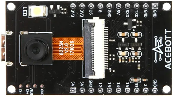
The Acebott ESP32 CAM V2 is a compact and versatile camera module powered by the ESP32 chip. It combines Wi-Fi and Bluetooth capabilities with image and video capture functionality, making it an ideal choice for IoT applications, surveillance systems, smart home devices, and AI-powered projects. Its small form factor and low power consumption make it suitable for embedded systems and portable devices.
Explore Projects Built with Acebott ESP32 cam
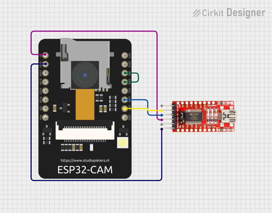
ESP32 CAM Wi-Fi Controlled Camera with FTDI Programmer

This circuit consists of an ESP32 CAM module connected to an FTDI Programmer for power and serial communication. The ESP32 CAM is programmed to capture images and stream them over WiFi, acting as a web server to provide live video feed.
ESP32 CAM Wi-Fi Controlled Camera with FTDI Programmer

This circuit consists of an ESP32 CAM module connected to an FTDI Programmer for power and serial communication. The ESP32 CAM is programmed to capture images and stream them over WiFi, acting as a web server to provide a live video feed.
ESP32 CAM Wi-Fi Controlled Live Video Streamer with FTDI Programmer
This circuit consists of an ESP32 CAM module connected to an FTDI Programmer for power and serial communication. The ESP32 CAM is programmed to capture images and stream them over WiFi, acting as a web server to provide a live video feed.
ESP32 CAM Wi-Fi Enabled Camera Module with USB Power

This circuit consists of an ESP32 CAM module powered by a Micro USB breakout board. The USB breakout board supplies 5V and ground to the ESP32 CAM, enabling it to function and perform tasks such as image capture and processing.
Explore Projects Built with Acebott ESP32 cam
ESP32 CAM Wi-Fi Controlled Camera with FTDI Programmer
This circuit consists of an ESP32 CAM module connected to an FTDI Programmer for power and serial communication. The ESP32 CAM is programmed to capture images and stream them over WiFi, acting as a web server to provide live video feed.
ESP32 CAM Wi-Fi Controlled Camera with FTDI Programmer
This circuit consists of an ESP32 CAM module connected to an FTDI Programmer for power and serial communication. The ESP32 CAM is programmed to capture images and stream them over WiFi, acting as a web server to provide a live video feed.
ESP32 CAM Wi-Fi Controlled Live Video Streamer with FTDI Programmer
This circuit consists of an ESP32 CAM module connected to an FTDI Programmer for power and serial communication. The ESP32 CAM is programmed to capture images and stream them over WiFi, acting as a web server to provide a live video feed.
ESP32 CAM Wi-Fi Enabled Camera Module with USB Power
This circuit consists of an ESP32 CAM module powered by a Micro USB breakout board. The USB breakout board supplies 5V and ground to the ESP32 CAM, enabling it to function and perform tasks such as image capture and processing.
Common Applications
- Wireless video streaming and surveillance
- Smart home automation (e.g., doorbell cameras, pet monitors)
- IoT projects requiring image or video capture
- AI and machine learning applications (e.g., facial recognition)
- Remote monitoring and control systems
Technical Specifications
Key Technical Details
| Parameter | Specification |
|---|---|
| Microcontroller | ESP32-D0WD |
| Wireless Connectivity | Wi-Fi 802.11 b/g/n, Bluetooth 4.2 |
| Camera Sensor | OV2640 |
| Image Resolution | Up to 1600x1200 (UXGA) |
| Flash Memory | 4 MB SPI Flash |
| RAM | 520 KB SRAM + 4 MB PSRAM |
| Operating Voltage | 3.3V |
| Power Consumption | ~160 mA (active), ~10 µA (deep sleep) |
| Interfaces | UART, SPI, I2C, PWM, GPIO |
| Dimensions | 27 mm x 40.5 mm |
Pin Configuration and Descriptions
| Pin Name | Pin Number | Description |
|---|---|---|
| 3V3 | 1 | 3.3V power input |
| GND | 2 | Ground |
| U0R | 3 | UART0 RX (used for programming) |
| U0T | 4 | UART0 TX (used for programming) |
| GPIO0 | 5 | Boot mode selection (connect to GND for flashing) |
| GPIO1 | 6 | General-purpose I/O |
| GPIO2 | 7 | General-purpose I/O |
| GPIO3 | 8 | General-purpose I/O |
| GPIO4 | 9 | General-purpose I/O |
| GPIO16 | 10 | General-purpose I/O |
| GPIO17 | 11 | General-purpose I/O |
| RESET | 12 | Reset pin |
Usage Instructions
How to Use the Acebott ESP32 CAM V2 in a Circuit
- Power Supply: Connect the 3V3 pin to a 3.3V power source and GND to ground.
- Programming: Use a USB-to-TTL converter to connect the U0R (RX) and U0T (TX) pins to your computer. Ensure GPIO0 is connected to GND during programming.
- Camera Module: The OV2640 camera module is pre-attached. Ensure it is securely connected to the board.
- Flashing Firmware:
- Install the ESP32 board package in the Arduino IDE.
- Select "AI-Thinker ESP32-CAM" as the board type.
- Upload your code using the USB-to-TTL converter.
- Wi-Fi Configuration: Include your Wi-Fi credentials in the code to enable wireless connectivity.
Important Considerations and Best Practices
- Power Supply: Ensure a stable 3.3V power source. Voltage fluctuations can cause instability.
- Heat Management: The ESP32 chip may heat up during operation. Ensure proper ventilation.
- Antenna Placement: For optimal Wi-Fi performance, avoid placing the module near metal objects or inside enclosures that block signals.
- Boot Mode: Always disconnect GPIO0 from GND after flashing to boot the module normally.
Example Code for Arduino UNO
Below is an example code to capture an image and serve it over a web server:
#include <WiFi.h>
#include <esp_camera.h>

// Replace with your Wi-Fi credentials
const char* ssid = "Your_SSID";
const char* password = "Your_PASSWORD";

// Camera configuration
#define PWDN_GPIO_NUM    -1
#define RESET_GPIO_NUM   -1
#define XCLK_GPIO_NUM     0
#define SIOD_GPIO_NUM    26
#define SIOC_GPIO_NUM    27
#define Y9_GPIO_NUM      35
#define Y8_GPIO_NUM      34
#define Y7_GPIO_NUM      39
#define Y6_GPIO_NUM      36
#define Y5_GPIO_NUM      21
#define Y4_GPIO_NUM      19
#define Y3_GPIO_NUM      18
#define Y2_GPIO_NUM       5
#define VSYNC_GPIO_NUM   25
#define HREF_GPIO_NUM    23
#define PCLK_GPIO_NUM    22

void startCameraServer();

void setup() {
  Serial.begin(115200);
  WiFi.begin(ssid, password);

  // Wait for Wi-Fi connection
  while (WiFi.status() != WL_CONNECTED) {
    delay(500);
    Serial.print(".");
  }
  Serial.println("\nWi-Fi connected!");

  // Initialize the camera
  camera_config_t config;
  config.ledc_channel = LEDC_CHANNEL_0;
  config.ledc_timer = LEDC_TIMER_0;
  config.pin_d0 = Y2_GPIO_NUM;
  config.pin_d1 = Y3_GPIO_NUM;
  config.pin_d2 = Y4_GPIO_NUM;
  config.pin_d3 = Y5_GPIO_NUM;
  config.pin_d4 = Y6_GPIO_NUM;
  config.pin_d5 = Y7_GPIO_NUM;
  config.pin_d6 = Y8_GPIO_NUM;
  config.pin_d7 = Y9_GPIO_NUM;
  config.pin_xclk = XCLK_GPIO_NUM;
  config.pin_pclk = PCLK_GPIO_NUM;
  config.pin_vsync = VSYNC_GPIO_NUM;
  config.pin_href = HREF_GPIO_NUM;
  config.pin_sscb_sda = SIOD_GPIO_NUM;
  config.pin_sscb_scl = SIOC_GPIO_NUM;
  config.pin_pwdn = PWDN_GPIO_NUM;
  config.pin_reset = RESET_GPIO_NUM;
  config.xclk_freq_hz = 20000000;
  config.pixel_format = PIXFORMAT_JPEG;

  if (!esp_camera_init(&config)) {
    Serial.println("Camera initialized successfully!");
  } else {
    Serial.println("Camera initialization failed!");
    return;
  }

  startCameraServer();
}

void loop() {
  // Main loop does nothing; camera server handles requests
}
Troubleshooting and FAQs
Common Issues
Camera Initialization Failed:
- Ensure the OV2640 module is securely connected.
- Verify the camera configuration pins in your code.
Wi-Fi Not Connecting:
- Double-check your SSID and password.
- Ensure the module is within range of your Wi-Fi router.
Module Not Detected During Programming:
- Ensure GPIO0 is connected to GND during flashing.
- Verify the USB-to-TTL converter connections.
Overheating:
- Provide adequate ventilation or a small heatsink for the ESP32 chip.
Tips for Troubleshooting
- Use a multimeter to check the power supply voltage.
- Monitor the serial output for error messages.
- Test the module with a simple "Blink" sketch to verify basic functionality.