How to Use AIR FLOW SENSOR: Examples, Pinouts, and Specs
Air Flow Sensor Documentation
1. Introduction
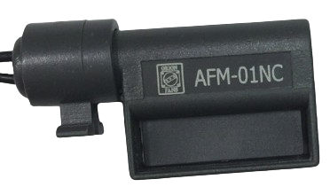
The Air Flow Sensor (Manufacturer: AIR FLOW SENSOR, Part ID: AIR FLOW SENSOR) is a precision device designed to measure the flow rate of air in a system. It is widely used in applications such as HVAC (Heating, Ventilation, and Air Conditioning) systems, automotive air intake monitoring, industrial process control, and environmental monitoring. By providing accurate air flow measurements, this sensor helps optimize system performance, improve energy efficiency, and ensure safety.
Common Applications:
- HVAC Systems: Monitoring and controlling air circulation in residential, commercial, and industrial environments.
- Automotive Systems: Measuring air intake in engines for fuel efficiency and emissions control.
- Industrial Processes: Ensuring proper air flow in manufacturing and production systems.
- Environmental Monitoring: Measuring air flow in ventilation systems or air quality monitoring stations.
2. Technical Specifications
The following table outlines the key technical specifications of the Air Flow Sensor:
| Parameter | Value |
|---|---|
| Operating Voltage | 5V DC |
| Operating Current | 20 mA (typical) |
| Output Signal Type | Analog Voltage (0.5V to 4.5V) |
| Measurement Range | 0 to 50 m/s (meters per second) |
| Accuracy | ±3% of full scale |
| Operating Temperature | -20°C to +85°C |
| Storage Temperature | -40°C to +100°C |
| Response Time | <10 ms |
| Connector Type | 3-pin (VCC, GND, OUT) |
Pin Configuration and Descriptions
| Pin Name | Pin Number | Description |
|---|---|---|
| VCC | 1 | Power supply input (5V DC) |
| GND | 2 | Ground connection |
| OUT | 3 | Analog output signal proportional to air flow |
3. Usage Instructions
Connecting the Air Flow Sensor to a Circuit
- Power Supply: Connect the VCC pin to a 5V DC power source and the GND pin to the ground of the circuit.
- Signal Output: Connect the OUT pin to an analog input pin of a microcontroller (e.g., Arduino UNO) or an ADC (Analog-to-Digital Converter) for signal processing.
- Calibration: For accurate measurements, calibrate the sensor in a controlled environment before use.
Important Considerations:
- Power Supply Stability: Ensure a stable 5V DC power supply to avoid signal noise or inaccuracies.
- Air Flow Direction: Install the sensor in the correct orientation as indicated by the manufacturer to ensure accurate readings.
- Environmental Conditions: Avoid exposing the sensor to extreme temperatures, humidity, or contaminants that may affect its performance.
- Signal Filtering: Use a low-pass filter if the output signal is noisy.
4. Example: Using the Air Flow Sensor with Arduino UNO
Below is an example of how to interface the Air Flow Sensor with an Arduino UNO to measure air flow and display the results on the Serial Monitor.
Circuit Diagram
- VCC → Arduino 5V
- GND → Arduino GND
- OUT → Arduino A0 (Analog Input)
Arduino Code
// Air Flow Sensor Example with Arduino UNO
// Reads the analog output of the sensor and calculates air flow in m/s

const int airFlowPin = A0; // Analog pin connected to the sensor's OUT pin
float voltage = 0.0;       // Variable to store the sensor's output voltage
float airFlow = 0.0;       // Variable to store the calculated air flow (m/s)

void setup() {
  Serial.begin(9600); // Initialize Serial Monitor at 9600 baud rate
  pinMode(airFlowPin, INPUT); // Set the sensor pin as input
}

void loop() {
  // Read the analog value from the sensor
  int sensorValue = analogRead(airFlowPin);

  // Convert the analog value to voltage (5V reference, 10-bit ADC)
  voltage = sensorValue * (5.0 / 1023.0);

  // Convert voltage to air flow (example formula: adjust based on sensor datasheet)
  // Assuming 0.5V = 0 m/s and 4.5V = 50 m/s
  airFlow = (voltage - 0.5) * (50.0 / (4.5 - 0.5));

  // Print the results to the Serial Monitor
  Serial.print("Voltage: ");
  Serial.print(voltage);
  Serial.print(" V, Air Flow: ");
  Serial.print(airFlow);
  Serial.println(" m/s");

  delay(500); // Wait for 500ms before the next reading
}
5. Troubleshooting and FAQs
Common Issues and Solutions
| Issue | Possible Cause | Solution |
|---|---|---|
| No output signal | Incorrect wiring or loose connections | Verify all connections and ensure proper wiring. |
| Inaccurate readings | Sensor not calibrated | Calibrate the sensor in a controlled environment. |
| Noisy output signal | Electrical interference or unstable power | Use a low-pass filter or stabilize the power supply. |
| Sensor not responding | Exceeded operating temperature range | Ensure the sensor is within the specified temperature range. |
Frequently Asked Questions (FAQs)
Q: Can this sensor measure air flow in both directions?
A: No, the sensor is designed to measure air flow in a specific direction. Ensure proper installation.Q: How do I calibrate the sensor?
A: Use a known air flow source and adjust the sensor's output to match the reference value.Q: Can I use this sensor with a 3.3V microcontroller?
A: The sensor requires a 5V power supply. Use a level shifter for compatibility with 3.3V systems.Q: What is the response time of the sensor?
A: The sensor has a response time of less than 10 milliseconds, making it suitable for real-time applications.
This documentation provides a comprehensive guide to understanding, using, and troubleshooting the Air Flow Sensor. For further assistance, refer to the manufacturer's datasheet or contact technical support.
Explore Projects Built with AIR FLOW SENSOR
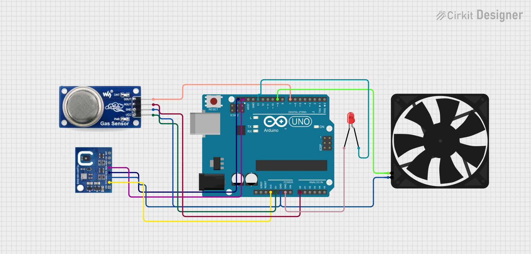
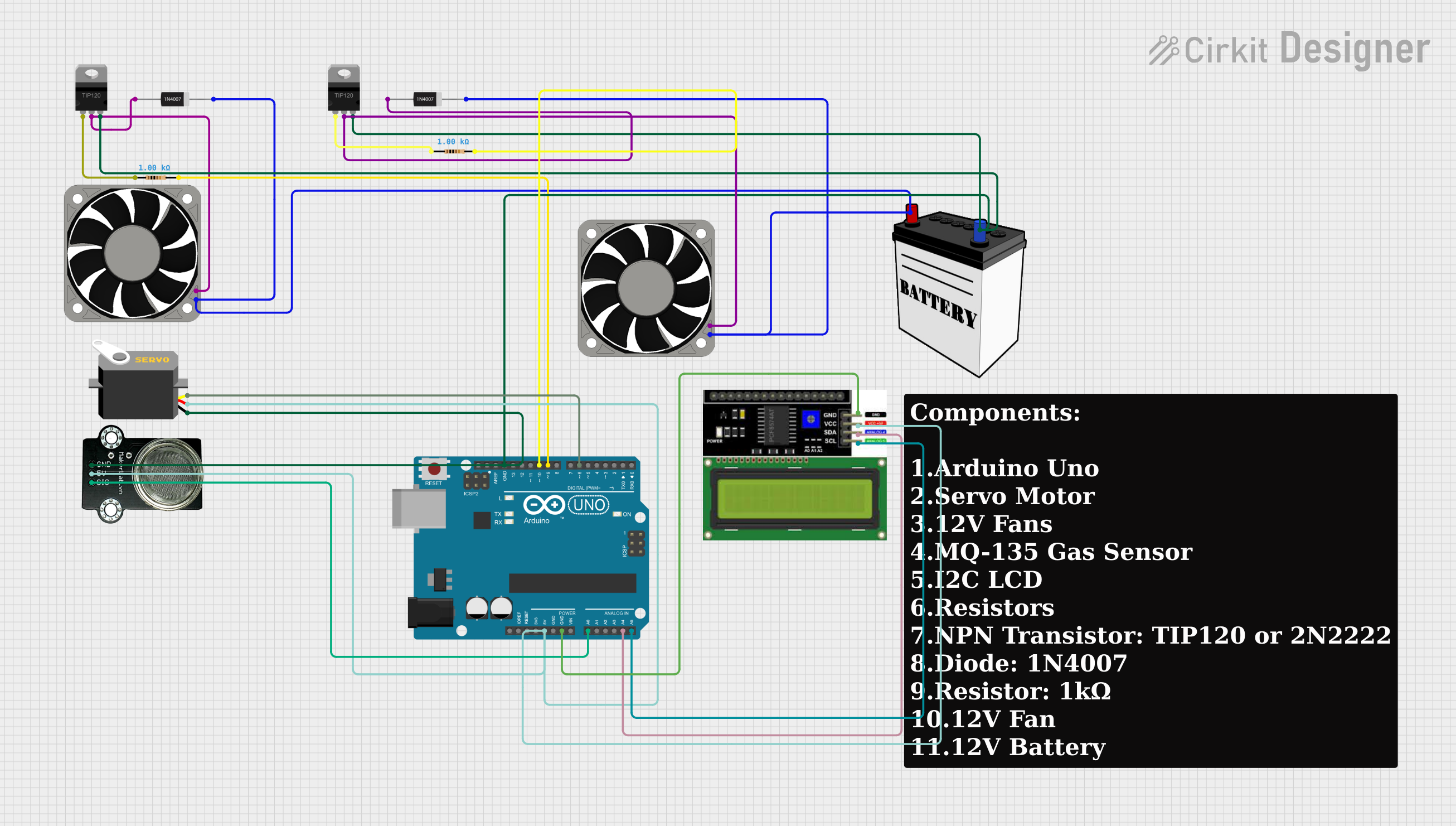
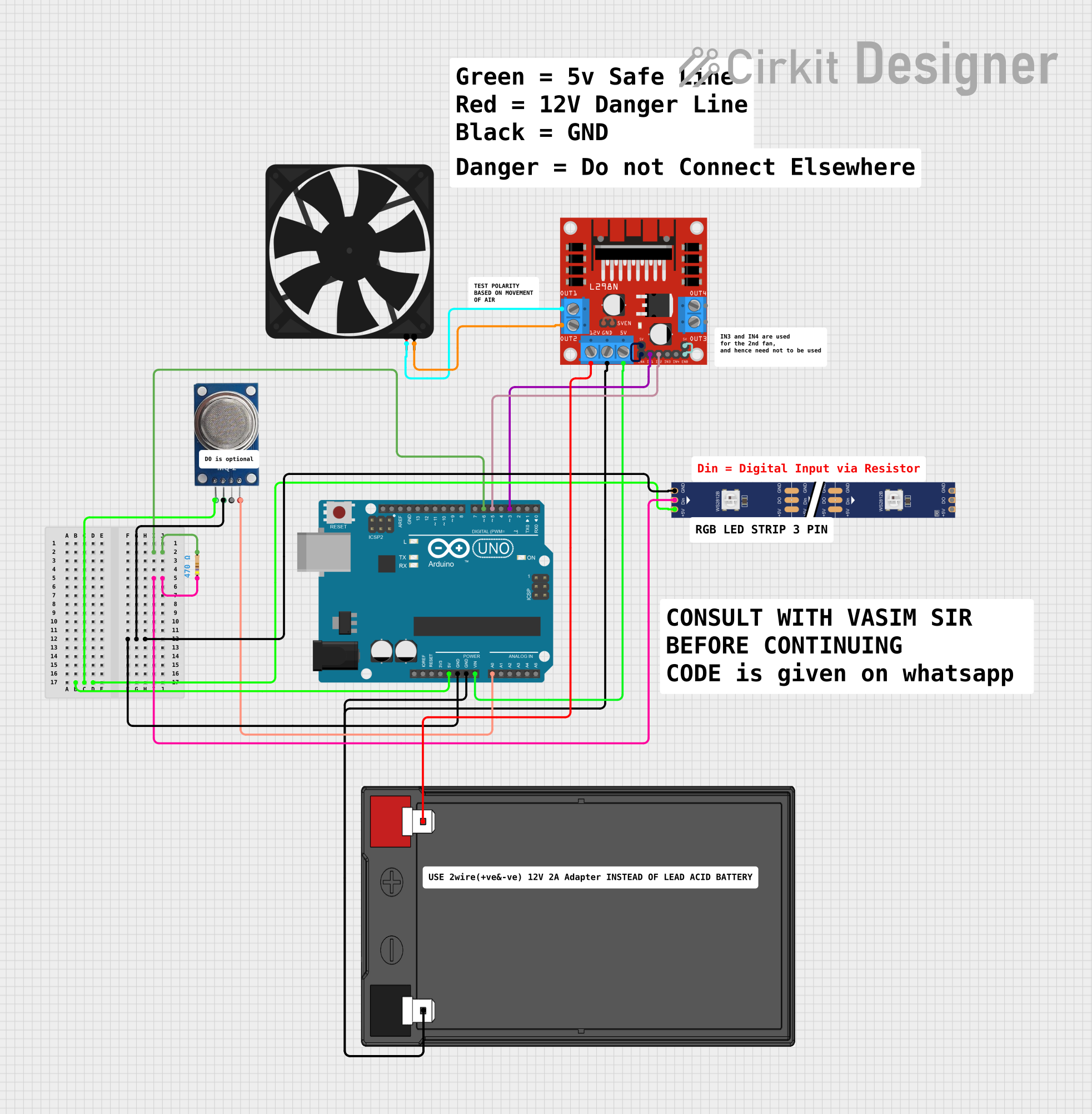
Explore Projects Built with AIR FLOW SENSOR