
How to Use Adafruit ISO1540: Examples, Pinouts, and Specs
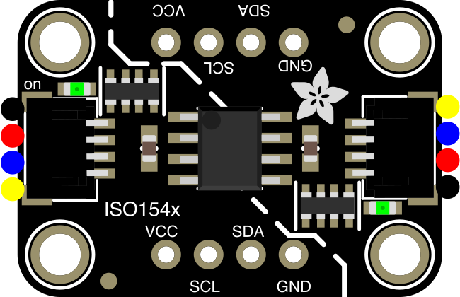
 Design with Adafruit ISO1540 in Cirkit Designer
Introduction
The Adafruit ISO1540 (Manufacturer Part ID: 4903) is an isolated I2C bus extender designed to enable communication between devices operating at different voltage levels while providing robust electrical isolation. This component is particularly useful in applications where sensitive electronics need protection from high voltages, noise, or ground loops. By isolating the I2C bus, the ISO1540 ensures safe and reliable data transfer in mixed-voltage environments.
Explore Projects Built with Adafruit ISO1540
 Open Project in Cirkit Designer
 Open Project in Cirkit Designer
 Open Project in Cirkit Designer
 Open Project in Cirkit Designer
Explore Projects Built with Adafruit ISO1540
Open Project in Cirkit DesignerOpen Project in Cirkit DesignerOpen Project in Cirkit DesignerOpen Project in Cirkit DesignerCommon Applications and Use Cases
- Industrial automation and control systems
- Medical devices requiring electrical isolation
- Communication between microcontrollers and high-voltage peripherals
- Noise-sensitive applications in harsh environments
- Systems requiring ground loop elimination
Technical Specifications
Key Technical Details
| Parameter | Value |
|---|---|
| Operating Voltage (Side A) | 2.25V to 5.5V |
| Operating Voltage (Side B) | 2.25V to 5.5V |
| Isolation Voltage | 2500 VRMS |
| Maximum I2C Speed | 1 Mbps |
| Operating Temperature | -40°C to +125°C |
| Package Type | SOIC-8 |
| Communication Protocol | I2C (bidirectional, isolated) |
Pin Configuration and Descriptions
| Pin Number | Pin Name | Description |
|---|---|---|
| 1 | VCC1 | Power supply for Side A (2.25V to 5.5V) |
| 2 | GND1 | Ground for Side A |
| 3 | SDA1 | I2C data line for Side A |
| 4 | SCL1 | I2C clock line for Side A |
| 5 | SDA2 | I2C data line for Side B |
| 6 | SCL2 | I2C clock line for Side B |
| 7 | GND2 | Ground for Side B |
| 8 | VCC2 | Power supply for Side B (2.25V to 5.5V) |
Usage Instructions
How to Use the Adafruit ISO1540 in a Circuit
Power Supply Connections:
- Connect
VCC1andGND1to the power supply for Side A. - Connect
VCC2andGND2to the power supply for Side B. - Ensure that the voltage levels on Side A and Side B are within the specified range (2.25V to 5.5V).
- Connect
I2C Bus Connections:
- Connect the I2C master or slave device on Side A to
SDA1andSCL1. - Connect the I2C master or slave device on Side B to
SDA2andSCL2.
- Connect the I2C master or slave device on Side A to
Pull-Up Resistors:
- Add appropriate pull-up resistors to the
SDAandSCLlines on both sides of the ISO1540. - The resistor values depend on the bus voltage and speed. Common values are 4.7kΩ or 10kΩ.
- Add appropriate pull-up resistors to the
Isolation:
- The ISO1540 provides electrical isolation between Side A and Side B. Ensure that the grounds (
GND1andGND2) are not directly connected.
- The ISO1540 provides electrical isolation between Side A and Side B. Ensure that the grounds (
Testing:
- Verify the connections and power up the circuit.
- Use an oscilloscope or logic analyzer to confirm proper I2C communication.
Important Considerations and Best Practices
- Ensure that the voltage levels on both sides of the ISO1540 are within the specified range.
- Use decoupling capacitors (e.g., 0.1µF) close to the
VCC1andVCC2pins to stabilize the power supply. - Avoid exceeding the maximum I2C speed of 1 Mbps.
- Do not connect the grounds of Side A and Side B to maintain isolation.
Example: Using the ISO1540 with an Arduino UNO
The following example demonstrates how to use the Adafruit ISO1540 to isolate an I2C sensor from an Arduino UNO.
Circuit Diagram
- Connect
VCC1to the Arduino's 5V pin andGND1to the Arduino's GND. - Connect
SDA1andSCL1to the Arduino'sA4andA5pins, respectively. - Connect
VCC2andGND2to the sensor's power supply. - Connect
SDA2andSCL2to the sensor's I2C lines.
Arduino Code
#include <Wire.h>

// I2C address of the sensor
#define SENSOR_ADDRESS 0x40

void setup() {
  Wire.begin(); // Initialize I2C communication
  Serial.begin(9600); // Start serial communication for debugging

  // Check if the sensor is connected
  Wire.beginTransmission(SENSOR_ADDRESS);
  if (Wire.endTransmission() == 0) {
    Serial.println("Sensor detected!");
  } else {
    Serial.println("Sensor not detected. Check connections.");
  }
}

void loop() {
  // Example: Read data from the sensor
  Wire.beginTransmission(SENSOR_ADDRESS);
  Wire.write(0x00); // Command to read data (sensor-specific)
  Wire.endTransmission();

  Wire.requestFrom(SENSOR_ADDRESS, 2); // Request 2 bytes of data
  if (Wire.available() == 2) {
    int data = Wire.read() << 8 | Wire.read(); // Combine two bytes
    Serial.print("Sensor Data: ");
    Serial.println(data);
  }

  delay(1000); // Wait 1 second before the next read
}
Troubleshooting and FAQs
Common Issues and Solutions
No Communication on the I2C Bus:
- Verify the pull-up resistors on both sides of the ISO1540.
- Check the power supply connections (
VCC1,GND1,VCC2,GND2). - Ensure that the I2C devices are correctly connected to the appropriate pins.
Data Corruption or Noise:
- Use shorter wires to reduce noise and signal degradation.
- Add decoupling capacitors near the power supply pins.
Ground Loop Issues:
- Ensure that the grounds of Side A and Side B are not connected.
Overheating:
- Check for excessive current draw or incorrect voltage levels.
FAQs
Q1: Can the ISO1540 be used with SPI or UART?
A1: No, the ISO1540 is specifically designed for I2C communication and does not support SPI or UART protocols.
Q2: What is the maximum cable length for the I2C bus?
A2: The maximum cable length depends on the pull-up resistor values, bus speed, and environmental noise. For standard I2C speeds (100 kHz), lengths up to 1 meter are typically reliable.
Q3: Can I use the ISO1540 with 3.3V and 5V devices?
A3: Yes, the ISO1540 supports mixed-voltage operation. Connect the 3.3V device to one side and the 5V device to the other side.
Q4: Does the ISO1540 require external isolation components?
A4: No, the ISO1540 has built-in isolation and does not require additional components for isolation.