Cirkit Designer
Your all-in-one circuit design IDE
Home /
Component Documentation
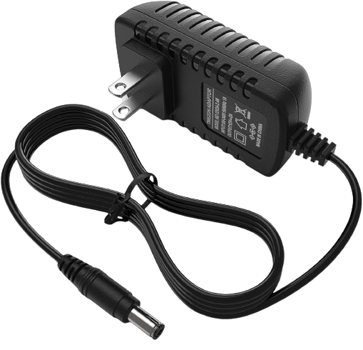
How to Use 12v power supply: Examples, Pinouts, and Specs
Introduction
A 12V power supply is an electronic device that converts input power into a stable 12-volt direct current (DC) output. It is widely used in various applications such as powering electronic circuits, computer peripherals, LED lighting systems, and other devices that require a consistent 12V DC power source.
Explore Projects Built with 12v power supply
12V UPS System with Dual 18650 Li-ion Battery Backup and Voltage Regulation

This circuit is designed to provide an uninterruptible power supply (UPS) system with a 12V DC output. It includes a 12V 5A power supply connected to an AC source through a toggle switch, which charges a pair of 18650 Li-ion batteries via a voltage regulator (XL4016). The UPS module ensures a continuous power supply to the load by switching between the power supply and the battery bank.
240V to 12V Power Conversion Circuit with Stopkontak
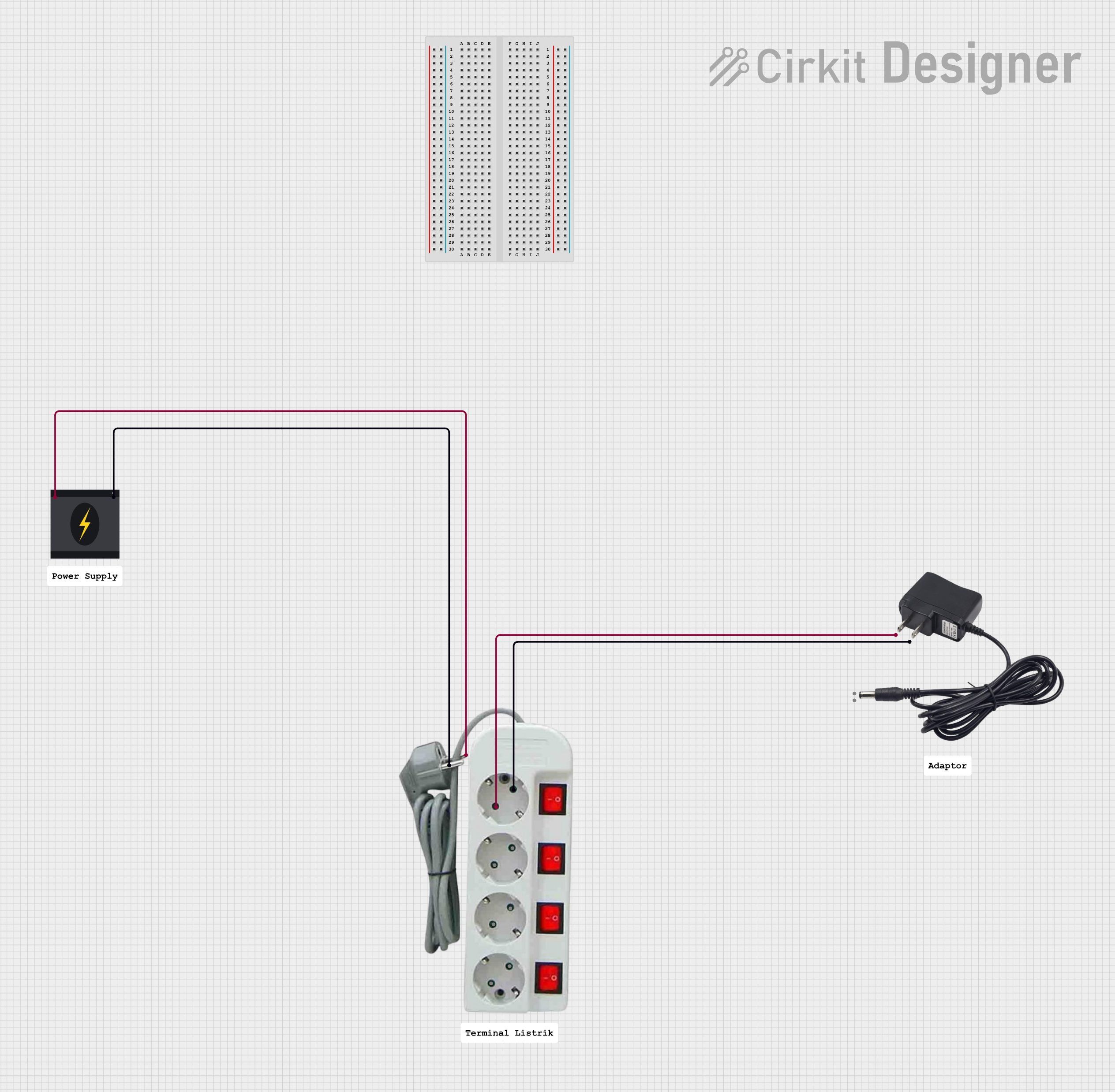
This circuit converts a 240V AC power source to a 12V DC output using a 12V adapter. The 240V AC power source is connected to a stopkontak, which then supplies the 12V adapter with the necessary AC voltage to produce a 12V DC output.
Adjustable LED Driver with LM317 Voltage Regulator and Potentiometer
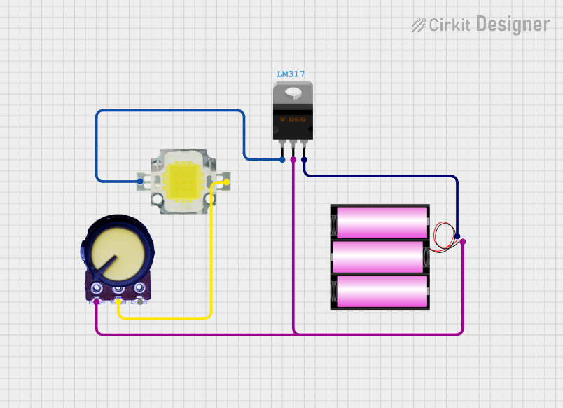
This circuit is a regulated power supply for a 12V, 10W LED, using an LM317 voltage regulator to control the output voltage. A potentiometer is used to adjust the voltage, and a 12V battery provides the input power.
12V to 5V Power Supply with LED Indicator and Push Switch

This circuit is a 12V to 5V regulated power supply with an LED indicator. It uses a 5408 diode for reverse polarity protection, an LM340T5 7805 voltage regulator to step down the voltage to 5V, and a push switch to control the LED indicator. The circuit also includes capacitors for filtering and a resistor to limit the current through the LED.
Explore Projects Built with 12v power supply
12V UPS System with Dual 18650 Li-ion Battery Backup and Voltage Regulation
This circuit is designed to provide an uninterruptible power supply (UPS) system with a 12V DC output. It includes a 12V 5A power supply connected to an AC source through a toggle switch, which charges a pair of 18650 Li-ion batteries via a voltage regulator (XL4016). The UPS module ensures a continuous power supply to the load by switching between the power supply and the battery bank.
240V to 12V Power Conversion Circuit with Stopkontak
This circuit converts a 240V AC power source to a 12V DC output using a 12V adapter. The 240V AC power source is connected to a stopkontak, which then supplies the 12V adapter with the necessary AC voltage to produce a 12V DC output.
Adjustable LED Driver with LM317 Voltage Regulator and Potentiometer
This circuit is a regulated power supply for a 12V, 10W LED, using an LM317 voltage regulator to control the output voltage. A potentiometer is used to adjust the voltage, and a 12V battery provides the input power.
12V to 5V Power Supply with LED Indicator and Push Switch
This circuit is a 12V to 5V regulated power supply with an LED indicator. It uses a 5408 diode for reverse polarity protection, an LM340T5 7805 voltage regulator to step down the voltage to 5V, and a push switch to control the LED indicator. The circuit also includes capacitors for filtering and a resistor to limit the current through the LED.
Common Applications and Use Cases
- Powering 12V DC motors
- LED strip lighting
- CCTV camera systems
- Automotive electronics
- Hobbyist electronics projects, including use with Arduino and Raspberry Pi
Technical Specifications
Key Technical Details
- Input Voltage: 100-240V AC (50/60Hz)
- Output Voltage: 12V DC
- Output Current: Varies by model (e.g., 1A, 2A, 5A)
- Power Ratings: Varies by model (e.g., 12W, 24W, 60W)
- Efficiency: >80% typically
- Operating Temperature: -10°C to +60°C
- Protection: Overvoltage, Overcurrent, Short Circuit, Overheat
Pin Configuration and Descriptions
| Pin No. | Description | Notes |
|---|---|---|
| 1 | AC Input (L) | Live wire of AC input |
| 2 | AC Input (N) | Neutral wire of AC input |
| 3 | Ground (⏚) | Protective earth ground |
| 4 | DC Output (+12V) | Positive terminal of DC output |
| 5 | DC Output (GND) | Ground terminal of DC output |
Usage Instructions
How to Use the Component in a Circuit
Connecting AC Input:
- Ensure the power supply is unplugged before wiring.
- Connect the live (L) and neutral (N) wires to the AC input pins.
- Attach the ground wire to the ground pin if available.
Connecting DC Output:
- Connect the positive terminal of your device to the +12V DC output pin.
- Connect the ground terminal of your device to the DC output ground pin.
Important Considerations and Best Practices
- Always verify the current and power ratings of your device to ensure the power supply can handle the load.
- Use a fuse or circuit breaker on the AC input for additional safety.
- Ensure proper ventilation around the power supply to prevent overheating.
- Do not exceed the rated output current of the power supply to avoid damage.
Troubleshooting and FAQs
Common Issues Users Might Face
- Power supply overheats: Ensure adequate ventilation and that the load does not exceed the power supply's ratings.
- No output voltage: Check AC input connections and verify that the power supply is receiving power.
- Voltage drop under load: Ensure that the power supply's current rating is sufficient for the load.
Solutions and Tips for Troubleshooting
- If the power supply is not turning on, check the AC input connections and the fuse.
- For voltage drops, consider using a power supply with a higher current rating or reduce the load.
- If the power supply overheats, remove any obstructions to airflow and consider adding additional cooling.
FAQs
Q: Can I use this power supply with an Arduino UNO?
- A: Yes, but ensure you regulate the voltage down to 5V using a voltage regulator or a buck converter.
Q: What should I do if the power supply makes noise?
- A: Some noise can be normal, but excessive noise may indicate an overload or a failing component. Reduce the load and check the power supply's health.
Example Arduino UNO Connection
// Example code to demonstrate how to power an Arduino UNO with a 12V power supply
// through the VIN pin. The Arduino UNO has an onboard voltage regulator that can
// handle input voltages from 7V to 12V.

void setup() {
  // Initialize digital pin LED_BUILTIN as an output.
  pinMode(LED_BUILTIN, OUTPUT);
}

void loop() {
  // Turn the LED on (HIGH is the voltage level)
  digitalWrite(LED_BUILTIN, HIGH);
  // Wait for a second
  delay(1000);
  // Turn the LED off by making the voltage LOW
  digitalWrite(LED_BUILTIN, LOW);
  // Wait for a second
  delay(1000);
}

// Note: When using a 12V power supply, connect the positive terminal to the
// Arduino's VIN pin and the ground to one of the Arduino's GND pins.
Remember to keep the power supply's current rating in mind when connecting additional components to the Arduino to prevent overloading the power supply.