Cirkit Designer Logo
Cirkit Designer
Your all-in-one circuit design IDE
Home / 
Component Documentation

How to Use ESP32-S3-DevKitC-1-N8R2: Examples, Pinouts, and Specs

Image of ESP32-S3-DevKitC-1-N8R2
Cirkit Designer LogoDesign with ESP32-S3-DevKitC-1-N8R2 in Cirkit Designer

Introduction

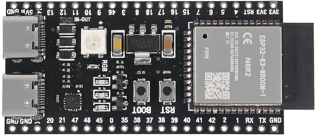
The ESP32-S3-DevKitC-1-N8R2 is a versatile development board from XIITIA, based on the ESP32-S3-WROOM-1 module. This board integrates a dual-core processor with Wi-Fi and Bluetooth capabilities, making it a powerful platform for Internet of Things (IoT) projects. It is widely used for applications such as smart home devices, industrial automation, and wearable electronics.

Explore Projects Built with ESP32-S3-DevKitC-1-N8R2

Use Cirkit Designer to design, explore, and prototype these projects online. Some projects support real-time simulation. Click "Open Project" to start designing instantly!
ESP32-Based GPS Tracker with SD Card Logging and Barometric Sensor
Image of gps projekt circuit: A project utilizing ESP32-S3-DevKitC-1-N8R2 in a practical application
This circuit features an ESP32 Wroom Dev Kit as the main microcontroller, interfaced with an MPL3115A2 sensor for pressure and temperature readings, and a Neo 6M GPS module for location tracking. The ESP32 is also connected to an SD card reader for data logging purposes. A voltage regulator is used to step down the USB power supply to 3.3V, which powers the ESP32, the sensor, and the SD card reader.
Cirkit Designer LogoOpen Project in Cirkit Designer
ESP32-Based Smart Agriculture System with LoRa Communication
Image of Soil Monitoring Device: A project utilizing ESP32-S3-DevKitC-1-N8R2 in a practical application
This circuit features an ESP32 Devkit V1 microcontroller as the central processing unit, interfacing with various sensors including a PH Meter, an NPK Soil Sensor, and a Soil Moisture Sensor for environmental data collection. It also includes an EBYTE LoRa E220 module for wireless communication. Power management is handled by a Step Up Boost Power Converter, which is connected to a 12V Battery, stepping up the voltage to power the ESP32 and sensors, with common ground connections throughout the circuit.
Cirkit Designer LogoOpen Project in Cirkit Designer
ESP32-S3 GPS and Wind Speed Logger with Dual OLED Displays and CAN Bus
Image of esp32-s3-ellipse: A project utilizing ESP32-S3-DevKitC-1-N8R2 in a practical application
This circuit features an ESP32-S3 microcontroller interfaced with an SD card module, two OLED displays, a GPS module, and a CAN bus module. The ESP32-S3 records GPS data to the SD card, displays speed on one OLED, and shows wind speed from the CAN bus on the other OLED, providing a comprehensive data logging and display system.
Cirkit Designer LogoOpen Project in Cirkit Designer
Battery-Powered ESP32-S3 Development Board Circuit
Image of my esp test: A project utilizing ESP32-S3-DevKitC-1-N8R2 in a practical application
This circuit consists of an ESP32-S3-DevKitC-1-N8R2 microcontroller powered by a 5V battery. The battery's positive terminal is connected to the 5Vin pin of the ESP32, and the negative terminal is connected to the GND pin, providing the necessary power for the microcontroller to operate.
Cirkit Designer LogoOpen Project in Cirkit Designer

Explore Projects Built with ESP32-S3-DevKitC-1-N8R2

Use Cirkit Designer to design, explore, and prototype these projects online. Some projects support real-time simulation. Click "Open Project" to start designing instantly!
Image of gps projekt circuit: A project utilizing ESP32-S3-DevKitC-1-N8R2 in a practical application
ESP32-Based GPS Tracker with SD Card Logging and Barometric Sensor
This circuit features an ESP32 Wroom Dev Kit as the main microcontroller, interfaced with an MPL3115A2 sensor for pressure and temperature readings, and a Neo 6M GPS module for location tracking. The ESP32 is also connected to an SD card reader for data logging purposes. A voltage regulator is used to step down the USB power supply to 3.3V, which powers the ESP32, the sensor, and the SD card reader.
Cirkit Designer LogoOpen Project in Cirkit Designer
Image of Soil Monitoring Device: A project utilizing ESP32-S3-DevKitC-1-N8R2 in a practical application
ESP32-Based Smart Agriculture System with LoRa Communication
This circuit features an ESP32 Devkit V1 microcontroller as the central processing unit, interfacing with various sensors including a PH Meter, an NPK Soil Sensor, and a Soil Moisture Sensor for environmental data collection. It also includes an EBYTE LoRa E220 module for wireless communication. Power management is handled by a Step Up Boost Power Converter, which is connected to a 12V Battery, stepping up the voltage to power the ESP32 and sensors, with common ground connections throughout the circuit.
Cirkit Designer LogoOpen Project in Cirkit Designer
Image of esp32-s3-ellipse: A project utilizing ESP32-S3-DevKitC-1-N8R2 in a practical application
ESP32-S3 GPS and Wind Speed Logger with Dual OLED Displays and CAN Bus
This circuit features an ESP32-S3 microcontroller interfaced with an SD card module, two OLED displays, a GPS module, and a CAN bus module. The ESP32-S3 records GPS data to the SD card, displays speed on one OLED, and shows wind speed from the CAN bus on the other OLED, providing a comprehensive data logging and display system.
Cirkit Designer LogoOpen Project in Cirkit Designer
Image of my esp test: A project utilizing ESP32-S3-DevKitC-1-N8R2 in a practical application
Battery-Powered ESP32-S3 Development Board Circuit
This circuit consists of an ESP32-S3-DevKitC-1-N8R2 microcontroller powered by a 5V battery. The battery's positive terminal is connected to the 5Vin pin of the ESP32, and the negative terminal is connected to the GND pin, providing the necessary power for the microcontroller to operate.
Cirkit Designer LogoOpen Project in Cirkit Designer

Technical Specifications

General Features

  • Processor: Xtensa® dual-core 32-bit LX7 microcontroller
  • Operating Voltage: 3.3V
  • Input Voltage: 5V via USB or Vin pin
  • Clock Frequency: Up to 240 MHz
  • Flash Memory: 8 MB
  • SRAM: 512 KB
  • Connectivity: Wi-Fi 802.11 b/g/n, Bluetooth v5.0 (BR/EDR and BLE)

Pin Configuration and Descriptions

Pin Number Name Description
1 3V3 3.3V power supply
2 GND Ground
3 EN Chip enable. Active high.
... ... ...
n IOxx General purpose IO pins

Note: This is a simplified representation. Refer to the official datasheet for the complete pinout and alternate functions.

Usage Instructions

Setting Up the Development Environment

  1. Install the latest version of the Arduino IDE or the ESP-IDF toolchain.
  2. Connect the ESP32-S3-DevKitC-1-N8R2 to your computer using a micro USB cable.
  3. Select the appropriate board and port in your development environment.

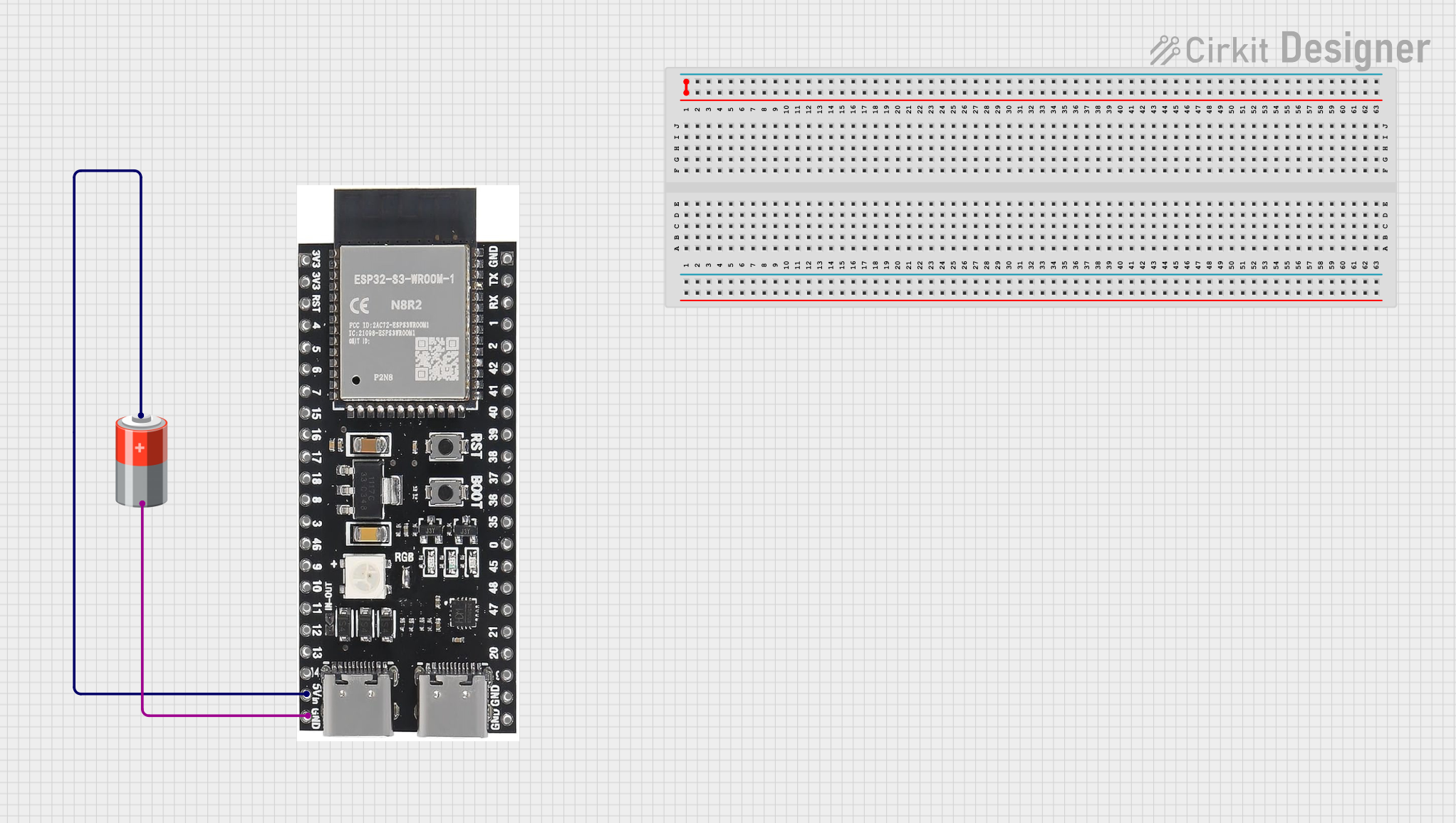
Basic Circuit Connection

To use the ESP32-S3-DevKitC-1-N8R2 in a circuit:

  1. Connect the 3V3 pin to the positive rail of your breadboard.
  2. Connect the GND pin to the negative rail of your breadboard.
  3. Interface the IO pins with other components as required for your project.

Best Practices

  • Ensure that the input voltage does not exceed the recommended 5V.
  • Use a current limiting resistor when connecting LEDs to the IO pins.
  • Avoid drawing more than 12 mA from any IO pin.

Example Code for Arduino IDE

#include <WiFi.h>

// Replace with your network credentials
const char* ssid = "your_SSID";
const char* password = "your_PASSWORD";

void setup() {
  Serial.begin(115200);
  
  // Connect to Wi-Fi
  WiFi.begin(ssid, password);
  while (WiFi.status() != WL_CONNECTED) {
    delay(500);
    Serial.println("Connecting to WiFi...");
  }
  Serial.println("Connected to WiFi");
}

void loop() {
  // Implement your logic here
}

Note: This example demonstrates how to connect the ESP32-S3-DevKitC-1-N8R2 to a Wi-Fi network.

Troubleshooting and FAQs

Common Issues

  • Device not recognized: Ensure the micro USB cable is properly connected and the computer has the necessary drivers installed.
  • Cannot upload sketch: Check the selected board and port in the Arduino IDE. Make sure the boot mode is correct.
  • Wi-Fi connection fails: Verify the SSID and password are correct. Ensure the Wi-Fi network is within range.

FAQs

  • Q: Can I power the ESP32-S3-DevKitC-1-N8R2 using batteries?

    • A: Yes, you can power the board using batteries, but ensure the voltage is regulated to 3.3V.
  • Q: How many GPIO pins are available for general use?

    • A: The board provides several GPIO pins. Refer to the datasheet for the exact count and their functions.
  • Q: What is the maximum current that can be sourced from a GPIO pin?

    • A: Each GPIO can source or sink up to 12 mA, but it's recommended to stay below this limit to prevent damage.

For more detailed troubleshooting, refer to the official forums and community guides related to the ESP32-S3-DevKitC-1-N8R2.