How to Use DM556 (Jiawen) Microstep Driver Peak 5.6A, 20-50 VDC 2-phase: Examples, Pinouts, and Specs
Introduction
The DM556 microstep driver, manufactured by Jiawen, is a high-performance driver designed for controlling 2-phase stepper motors. It supports a wide range of step resolutions and delivers smooth motion with high precision. With a peak current of 5.6A and an operating voltage range of 20-50 VDC, the DM556 is suitable for demanding applications requiring precise motor control.
Explore Projects Built with DM556 (Jiawen) Microstep Driver Peak 5.6A, 20-50 VDC 2-phase


Explore Projects Built with DM556 (Jiawen) Microstep Driver Peak 5.6A, 20-50 VDC 2-phase
Common Applications and Use Cases
- CNC machines and 3D printers
- Robotics and automation systems
- Laser cutters and engravers
- Conveyor systems
- Industrial machinery requiring precise motion control
Technical Specifications
Key Technical Details
| Parameter | Value |
|---|---|
| Manufacturer | Jiawen |
| Part ID | DM556 |
| Input Voltage Range | 20-50 VDC |
| Peak Output Current | 5.6A |
| Microstepping Resolution | Up to 256 microsteps per step |
| Motor Type Supported | 2-phase stepper motors |
| Control Signal Voltage | 5V TTL |
| Operating Temperature | -10°C to +45°C |
| Dimensions | 118mm x 75.5mm x 34mm |
| Weight | 280g |
Pin Configuration and Descriptions
The DM556 has two main connectors: one for motor and power connections, and another for control signals. Below is the pin configuration:
Motor and Power Connector
| Pin Name | Description |
|---|---|
| A+ | Positive terminal for motor coil A |
| A- | Negative terminal for motor coil A |
| B+ | Positive terminal for motor coil B |
| B- | Negative terminal for motor coil B |
| V+ | Positive power supply input (20-50V) |
| GND | Ground for power supply |
Control Signal Connector
| Pin Name | Description |
|---|---|
| PUL+ | Positive pulse signal input (step signal) |
| PUL- | Negative pulse signal input |
| DIR+ | Positive direction signal input |
| DIR- | Negative direction signal input |
| ENA+ | Positive enable signal input (optional) |
| ENA- | Negative enable signal input (optional) |
Usage Instructions
How to Use the DM556 in a Circuit
- Power Supply: Connect a DC power supply (20-50 VDC) to the
V+andGNDpins. Ensure the power supply can deliver sufficient current for the motor and driver. - Motor Connection: Connect the stepper motor coils to the
A+,A-,B+, andB-terminals. Verify the wiring matches the motor's datasheet. - Control Signals: Connect the
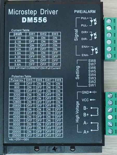
PUL+,PUL-,DIR+, andDIR-pins to a microcontroller or motion controller. Use theENA+andENA-pins if you need to enable or disable the driver dynamically. - Microstepping and Current Settings: Use the DIP switches on the driver to configure the microstepping resolution and output current. Refer to the DM556 datasheet for detailed DIP switch settings.
Important Considerations and Best Practices
- Heat Dissipation: The DM556 may generate heat during operation. Mount it on a heat sink or ensure proper ventilation to prevent overheating.
- Signal Integrity: Use shielded cables for control signals to minimize noise interference.
- Current Settings: Set the output current to match the stepper motor's rated current to avoid damage to the motor or driver.
- Microstepping: Choose an appropriate microstepping resolution based on the application's precision and speed requirements.
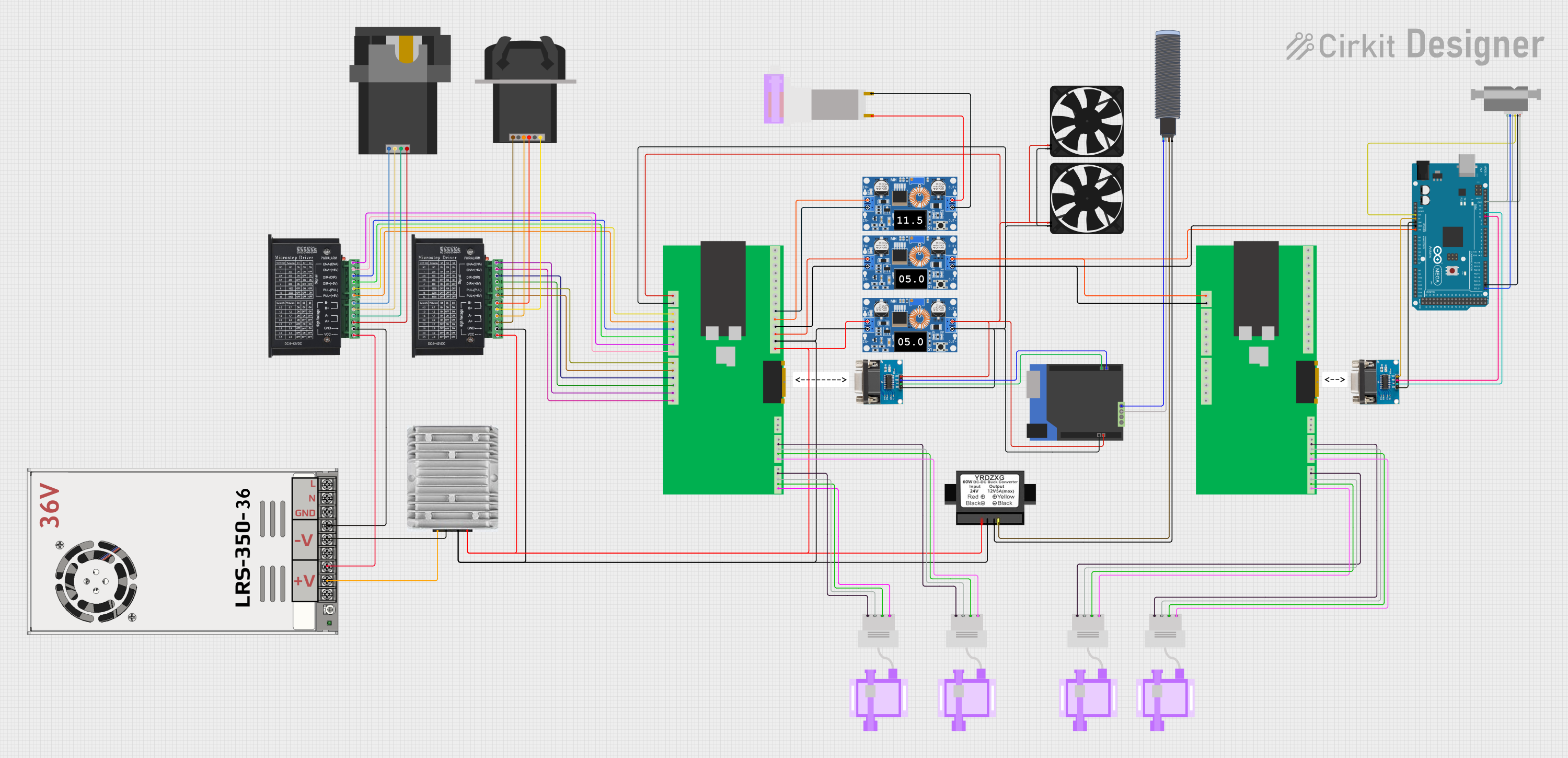
Example: Connecting the DM556 to an Arduino UNO
Below is an example of how to control the DM556 using an Arduino UNO:
Wiring Diagram
PUL+to ArduinoD2PUL-to ArduinoGNDDIR+to ArduinoD3DIR-to ArduinoGNDENA+to ArduinoD4(optional)ENA-to ArduinoGND- Connect the motor and power supply as described above.
Arduino Code
// Define pin connections
const int stepPin = 2;  // Pin connected to PUL+
const int dirPin = 3;   // Pin connected to DIR+
const int enablePin = 4; // Pin connected to ENA+ (optional)

void setup() {
  // Set pin modes
  pinMode(stepPin, OUTPUT);
  pinMode(dirPin, OUTPUT);
  pinMode(enablePin, OUTPUT);

  // Enable the driver
  digitalWrite(enablePin, LOW); // LOW to enable, HIGH to disable
}

void loop() {
  // Set direction
  digitalWrite(dirPin, HIGH); // HIGH for one direction, LOW for the other

  // Generate step pulses
  for (int i = 0; i < 200; i++) { // 200 steps for one revolution (1.8° motor)
    digitalWrite(stepPin, HIGH);
    delayMicroseconds(500); // Adjust for speed
    digitalWrite(stepPin, LOW);
    delayMicroseconds(500);
  }

  delay(1000); // Wait 1 second before reversing direction

  // Reverse direction
  digitalWrite(dirPin, LOW);
  for (int i = 0; i < 200; i++) {
    digitalWrite(stepPin, HIGH);
    delayMicroseconds(500);
    digitalWrite(stepPin, LOW);
    delayMicroseconds(500);
  }

  delay(1000); // Wait 1 second before repeating
}
Troubleshooting and FAQs
Common Issues and Solutions
Motor Not Moving
- Cause: Incorrect wiring or loose connections.
- Solution: Double-check all connections, especially motor coils and control signals.
Driver Overheating
- Cause: Insufficient cooling or incorrect current settings.
- Solution: Ensure proper ventilation or use a heat sink. Set the current to match the motor's rated current.
Erratic Motor Movement
- Cause: Noise interference or incorrect microstepping settings.
- Solution: Use shielded cables for control signals and verify DIP switch settings.
No Response from Driver
- Cause: Driver not enabled or incorrect power supply voltage.
- Solution: Check the
ENA+andENA-signals. Verify the power supply voltage is within the 20-50 VDC range.
FAQs
Can the DM556 drive 3-phase stepper motors?
- No, the DM556 is designed specifically for 2-phase stepper motors.
What is the maximum microstepping resolution?
- The DM556 supports up to 256 microsteps per step.
Is the driver compatible with 12V power supplies?
- No, the minimum input voltage is 20V. Using a 12V supply may damage the driver.
Can I use the DM556 without the enable pins?
- Yes, the driver is enabled by default if the
ENA+andENA-pins are not connected.
- Yes, the driver is enabled by default if the