How to Use MAX6675: Examples, Pinouts, and Specs
Introduction
The MAX6675 is a digital thermocouple-to-digital converter manufactured by Maxim Integrated. It is designed to measure temperatures in the range of 0°C to 1024°C using a K-type thermocouple. The device provides a 12-bit resolution digital output via an SPI-compatible interface, making it easy to integrate with microcontrollers and other digital systems.
Explore Projects Built with MAX6675


Explore Projects Built with MAX6675
Common Applications and Use Cases
- Industrial temperature monitoring
- HVAC systems
- Home appliances (e.g., ovens, heaters)
- Scientific instrumentation
- Data logging systems
- Embedded systems requiring precise temperature measurements
Technical Specifications
The MAX6675 is a robust and reliable component with the following key specifications:
| Parameter | Value |
|---|---|
| Temperature Range | 0°C to 1024°C |
| Resolution | 12-bit (0.25°C per bit) |
| Thermocouple Type | K-Type |
| Supply Voltage (Vcc) | 3.0V to 5.5V |
| Supply Current | 1.5mA (typical) |
| Communication Interface | SPI-compatible (3-wire) |
| Conversion Time | 220ms |
| Operating Temperature Range | -20°C to +85°C |
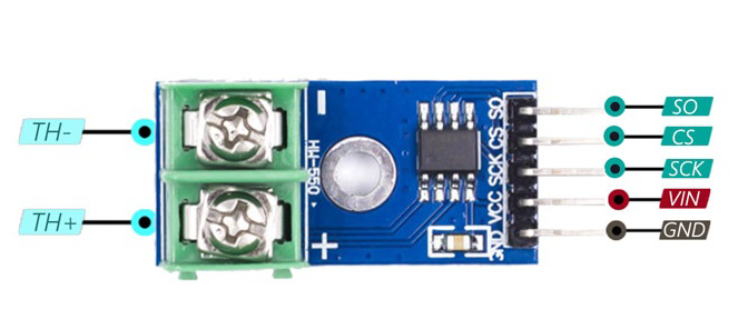
Pin Configuration and Descriptions
The MAX6675 has 8 pins, as described in the table below:
| Pin Number | Pin Name | Description |
|---|---|---|
| 1 | T- | Negative terminal of the K-type thermocouple |
| 2 | T+ | Positive terminal of the K-type thermocouple |
| 3 | GND | Ground connection |
| 4 | Vcc | Power supply input (3.0V to 5.5V) |
| 5 | SO | Serial data output (SPI-compatible) |
| 6 | CS | Chip Select (active low, used to enable communication with the MAX6675) |
| 7 | SCK | Serial Clock Input (SPI clock signal from the microcontroller) |
| 8 | NC | No Connection (not used, leave unconnected) |
Usage Instructions
The MAX6675 is straightforward to use in a circuit, especially when interfacing with microcontrollers like the Arduino UNO. Below are the steps and best practices for using the MAX6675:
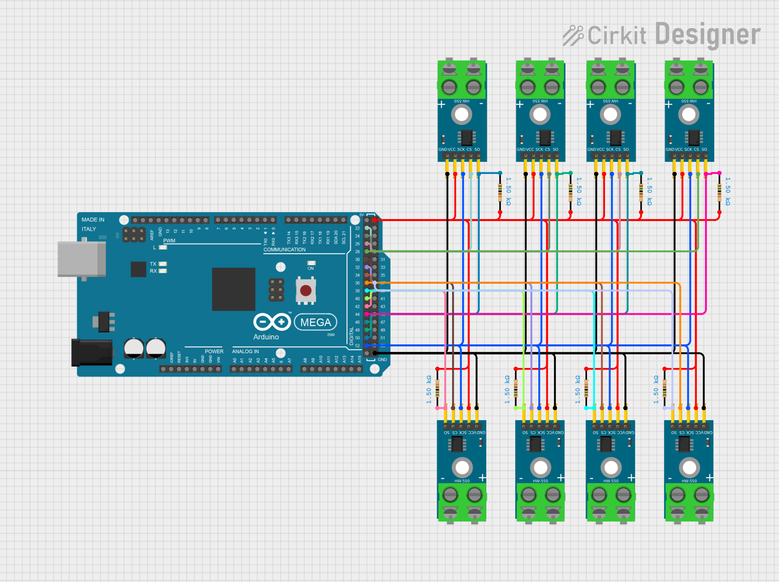
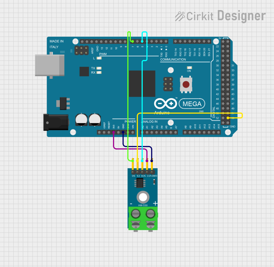
Circuit Connection
- Connect the K-type thermocouple to the
T+andT-pins of the MAX6675. - Provide a stable power supply (3.0V to 5.5V) to the
Vccpin and connect theGNDpin to the ground of the circuit. - Connect the
SO,CS, andSCKpins to the corresponding SPI pins on the microcontroller:SO→ MISO (Master In Slave Out)CS→ Any digital pin (e.g., D10 on Arduino UNO)SCK→ SCK (SPI Clock, D13 on Arduino UNO)
- Leave the
NCpin unconnected.
Arduino UNO Example Code
Below is an example of how to interface the MAX6675 with an Arduino UNO to read temperature data:
#include <SPI.h>

// Define MAX6675 connections
const int CS_PIN = 10; // Chip Select pin connected to D10

void setup() {
  Serial.begin(9600); // Initialize serial communication
  pinMode(CS_PIN, OUTPUT); // Set CS pin as output
  digitalWrite(CS_PIN, HIGH); // Set CS pin high (inactive)
  SPI.begin(); // Initialize SPI communication
}

float readTemperature() {
  uint16_t rawData;

  // Start communication with MAX6675
  digitalWrite(CS_PIN, LOW);
  delay(1); // Small delay to ensure proper communication

  // Read 16 bits of data from the MAX6675
  rawData = SPI.transfer(0x00) << 8; // Read high byte
  rawData |= SPI.transfer(0x00);    // Read low byte

  digitalWrite(CS_PIN, HIGH); // End communication

  // Check for thermocouple connection error
  if (rawData & 0x0004) {
    return NAN; // Return NaN if no thermocouple is connected
  }

  // Extract temperature data (bits 3 to 14) and convert to Celsius
  rawData >>= 3; // Shift right to remove unused bits
  return rawData * 0.25; // Each bit represents 0.25°C
}

void loop() {
  float temperature = readTemperature();

  if (isnan(temperature)) {
    Serial.println("Thermocouple not connected!");
  } else {
    Serial.print("Temperature: ");
    Serial.print(temperature);
    Serial.println(" °C");
  }

  delay(1000); // Wait 1 second before the next reading
}
Important Considerations and Best Practices
- Ensure the thermocouple is properly connected to the
T+andT-pins. Reversing the polarity will result in incorrect readings. - Use a stable power supply to minimize noise and ensure accurate temperature measurements.
- Avoid placing the MAX6675 near high-frequency or high-power components to reduce interference.
- The MAX6675 is designed for K-type thermocouples only. Using other types of thermocouples will result in inaccurate readings.
- The device has a built-in cold-junction compensation feature, so no external compensation is required.
Troubleshooting and FAQs
Common Issues and Solutions
| Issue | Possible Cause | Solution |
|---|---|---|
| No temperature reading (NaN displayed) | Thermocouple not connected or damaged | Verify the thermocouple connection and ensure it is functional. |
| Incorrect temperature readings | Reversed thermocouple polarity | Ensure the T+ and T- pins are connected to the correct thermocouple wires. |
| Unstable or noisy readings | Electrical noise or unstable power supply | Use decoupling capacitors near the Vcc pin and ensure a clean power source. |
| SPI communication not working | Incorrect wiring or SPI settings | Double-check the connections and ensure the SPI clock speed is within limits. |
| Temperature stuck at 0°C | Thermocouple wires shorted | Inspect the thermocouple for shorts and replace if necessary. |
FAQs
Can I use the MAX6675 with a 3.3V microcontroller?
Yes, the MAX6675 operates with a supply voltage of 3.0V to 5.5V, making it compatible with 3.3V systems.What happens if the thermocouple is disconnected?
The MAX6675 sets the fault bit in the output data, and the temperature reading will be invalid (NaN in the example code).Can I use a different type of thermocouple with the MAX6675?
No, the MAX6675 is specifically designed for K-type thermocouples. Using other types will result in inaccurate readings.What is the maximum SPI clock speed for the MAX6675?
The MAX6675 supports SPI clock speeds up to 4.3MHz.
By following this documentation, you can effectively integrate the MAX6675 into your projects for accurate and reliable temperature measurements.