Cirkit Designer Logo
Cirkit Designer
Your all-in-one circuit design IDE
Home / 
Component Documentation

How to Use parts/Adafruit NeoDriver STEMMA QT: Examples, Pinouts, and Specs

Image of parts/Adafruit NeoDriver STEMMA QT
Cirkit Designer LogoDesign with parts/Adafruit NeoDriver STEMMA QT in Cirkit Designer

Introduction

The Adafruit NeoDriver STEMMA QT is a versatile driver board designed for controlling NeoPixel LEDs. It features STEMMA QT connectors, which facilitate easy daisy-chaining and I2C communication. This component is ideal for projects requiring precise control of multiple NeoPixel LEDs, such as decorative lighting, displays, and interactive installations.

Explore Projects Built with parts/Adafruit NeoDriver STEMMA QT

Use Cirkit Designer to design, explore, and prototype these projects online. Some projects support real-time simulation. Click "Open Project" to start designing instantly!
Adafruit MPU6050 and VL6180X Sensor Interface with Servo Control
Image of wire: A project utilizing parts/Adafruit NeoDriver STEMMA QT in a practical application
This circuit features an Adafruit QT Py microcontroller interfaced with an Adafruit MPU6050 6-axis accelerometer/gyroscope and an Adafruit VL6180X Time of Flight (ToF) distance sensor, both connected via I2C communication. The QT Py also controls a Servomotor SG90, likely for physical actuation based on sensor inputs. The embedded code initializes the sensors, reads their data, and outputs the readings to a serial monitor, with the potential for motion control based on the sensor feedback.
Cirkit Designer LogoOpen Project in Cirkit Designer
Battery-Powered Smart Light with Proximity Sensor and OLED Display using Adafruit QT Py RP2040
Image of lab: A project utilizing parts/Adafruit NeoDriver STEMMA QT in a practical application
This circuit is a portable, battery-powered system featuring an Adafruit QT Py RP2040 microcontroller that interfaces with an OLED display, a proximity sensor, an accelerometer, and an RGB LED strip. The system is powered by a lithium-ion battery with a step-up boost converter to provide 5V for the LED strip, and it includes a toggle switch for power control. The microcontroller communicates with the sensors and display via I2C.
Cirkit Designer LogoOpen Project in Cirkit Designer
Battery-Powered Sensor Hub with Adafruit QT Py RP2040 and OLED Display
Image of 512: A project utilizing parts/Adafruit NeoDriver STEMMA QT in a practical application
This circuit features an Adafruit QT Py RP2040 microcontroller interfacing with an MPU-6050 accelerometer, an Adafruit APDS-9960 sensor, and a 0.96" OLED display via I2C communication. It is powered by a 3.7V LiPo battery and includes a green LED with a current-limiting resistor connected to an analog pin of the microcontroller.
Cirkit Designer LogoOpen Project in Cirkit Designer
Battery-Powered Smart Sensor Hub with Adafruit QT Py RP2040
Image of wearable final: A project utilizing parts/Adafruit NeoDriver STEMMA QT in a practical application
This circuit features an Adafruit QT Py RP2040 microcontroller interfaced with an APDS9960 proximity sensor, an MPU6050 accelerometer and gyroscope, and an OLED display via I2C communication. It also includes a buzzer controlled by the microcontroller and is powered by a 3.7V LiPo battery with a toggle switch for power control.
Cirkit Designer LogoOpen Project in Cirkit Designer

Explore Projects Built with parts/Adafruit NeoDriver STEMMA QT

Use Cirkit Designer to design, explore, and prototype these projects online. Some projects support real-time simulation. Click "Open Project" to start designing instantly!
Image of wire: A project utilizing parts/Adafruit NeoDriver STEMMA QT in a practical application
Adafruit MPU6050 and VL6180X Sensor Interface with Servo Control
This circuit features an Adafruit QT Py microcontroller interfaced with an Adafruit MPU6050 6-axis accelerometer/gyroscope and an Adafruit VL6180X Time of Flight (ToF) distance sensor, both connected via I2C communication. The QT Py also controls a Servomotor SG90, likely for physical actuation based on sensor inputs. The embedded code initializes the sensors, reads their data, and outputs the readings to a serial monitor, with the potential for motion control based on the sensor feedback.
Cirkit Designer LogoOpen Project in Cirkit Designer
Image of lab: A project utilizing parts/Adafruit NeoDriver STEMMA QT in a practical application
Battery-Powered Smart Light with Proximity Sensor and OLED Display using Adafruit QT Py RP2040
This circuit is a portable, battery-powered system featuring an Adafruit QT Py RP2040 microcontroller that interfaces with an OLED display, a proximity sensor, an accelerometer, and an RGB LED strip. The system is powered by a lithium-ion battery with a step-up boost converter to provide 5V for the LED strip, and it includes a toggle switch for power control. The microcontroller communicates with the sensors and display via I2C.
Cirkit Designer LogoOpen Project in Cirkit Designer
Image of 512: A project utilizing parts/Adafruit NeoDriver STEMMA QT in a practical application
Battery-Powered Sensor Hub with Adafruit QT Py RP2040 and OLED Display
This circuit features an Adafruit QT Py RP2040 microcontroller interfacing with an MPU-6050 accelerometer, an Adafruit APDS-9960 sensor, and a 0.96" OLED display via I2C communication. It is powered by a 3.7V LiPo battery and includes a green LED with a current-limiting resistor connected to an analog pin of the microcontroller.
Cirkit Designer LogoOpen Project in Cirkit Designer
Image of wearable final: A project utilizing parts/Adafruit NeoDriver STEMMA QT in a practical application
Battery-Powered Smart Sensor Hub with Adafruit QT Py RP2040
This circuit features an Adafruit QT Py RP2040 microcontroller interfaced with an APDS9960 proximity sensor, an MPU6050 accelerometer and gyroscope, and an OLED display via I2C communication. It also includes a buzzer controlled by the microcontroller and is powered by a 3.7V LiPo battery with a toggle switch for power control.
Cirkit Designer LogoOpen Project in Cirkit Designer

Technical Specifications

Key Technical Details

Parameter Value
Operating Voltage 3.3V to 5V
Communication I2C
I2C Address 0x40 (default)
Current Consumption Up to 1A (depending on load)
Dimensions 25mm x 25mm x 4mm

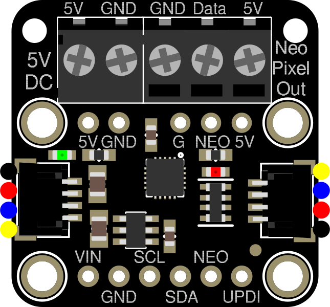
Pin Configuration and Descriptions

Pin Name Description
VIN Power input (3.3V to 5V)
GND Ground
SCL I2C clock line
SDA I2C data line
STEMMA QT Connectors for daisy-chaining and I2C communication

Usage Instructions

How to Use the Component in a Circuit

  1. Power Supply: Connect the VIN pin to a 3.3V or 5V power source and the GND pin to the ground.
  2. I2C Communication: Connect the SCL and SDA pins to the corresponding pins on your microcontroller (e.g., Arduino UNO).
  3. NeoPixel Connection: Connect the NeoPixel LED strip to the output pins of the NeoDriver.
  4. Daisy-Chaining: Use the STEMMA QT connectors to daisy-chain multiple NeoDriver boards if needed.

Important Considerations and Best Practices

  • Power Supply: Ensure that your power supply can handle the current requirements of the NeoPixel LEDs.
  • I2C Address: The default I2C address is 0x40. If you are using multiple NeoDriver boards, ensure each has a unique address.
  • Heat Management: High current loads can generate heat. Ensure adequate ventilation or heat dissipation.

Example Code for Arduino UNO

#include <Wire.h>
#include <Adafruit_NeoPixel.h>

#define I2C_ADDRESS 0x40 // Default I2C address for NeoDriver
#define PIN 6           // Pin connected to NeoPixel strip

Adafruit_NeoPixel strip = Adafruit_NeoPixel(30, PIN, NEO_GRB + NEO_KHZ800);

void setup() {
  Wire.begin(); // Initialize I2C communication
  strip.begin(); // Initialize NeoPixel strip
  strip.show();  // Initialize all pixels to 'off'
}

void loop() {
  for (int i = 0; i < strip.numPixels(); i++) {
    strip.setPixelColor(i, strip.Color(255, 0, 0)); // Set pixel to red
    strip.show(); // Update strip to show new color
    delay(50);    // Short delay to create animation effect
  }
}

Troubleshooting and FAQs

Common Issues Users Might Face

  1. No Response from NeoPixel LEDs:

    • Solution: Check the power connections and ensure the NeoPixel strip is properly connected to the NeoDriver.
  2. I2C Communication Failure:

    • Solution: Verify the I2C connections (SCL and SDA) and ensure the correct I2C address is used in the code.
  3. Overheating:

    • Solution: Ensure the power supply can handle the current load and provide adequate ventilation.

FAQs

Q1: Can I use a different I2C address for multiple NeoDriver boards?

  • A1: Yes, you can change the I2C address by modifying the address jumpers on the board.

Q2: What is the maximum number of NeoPixel LEDs I can control with one NeoDriver?

  • A2: The maximum number depends on the power supply and current requirements. Ensure your power supply can handle the total current draw.

Q3: Can I use the NeoDriver with microcontrollers other than Arduino?

  • A3: Yes, the NeoDriver can be used with any microcontroller that supports I2C communication.

This documentation provides a comprehensive guide to using the Adafruit NeoDriver STEMMA QT. Whether you are a beginner or an experienced user, following these instructions will help you effectively integrate this component into your projects.