How to Use Adafruit Airlift Shield: Examples, Pinouts, and Specs
Introduction
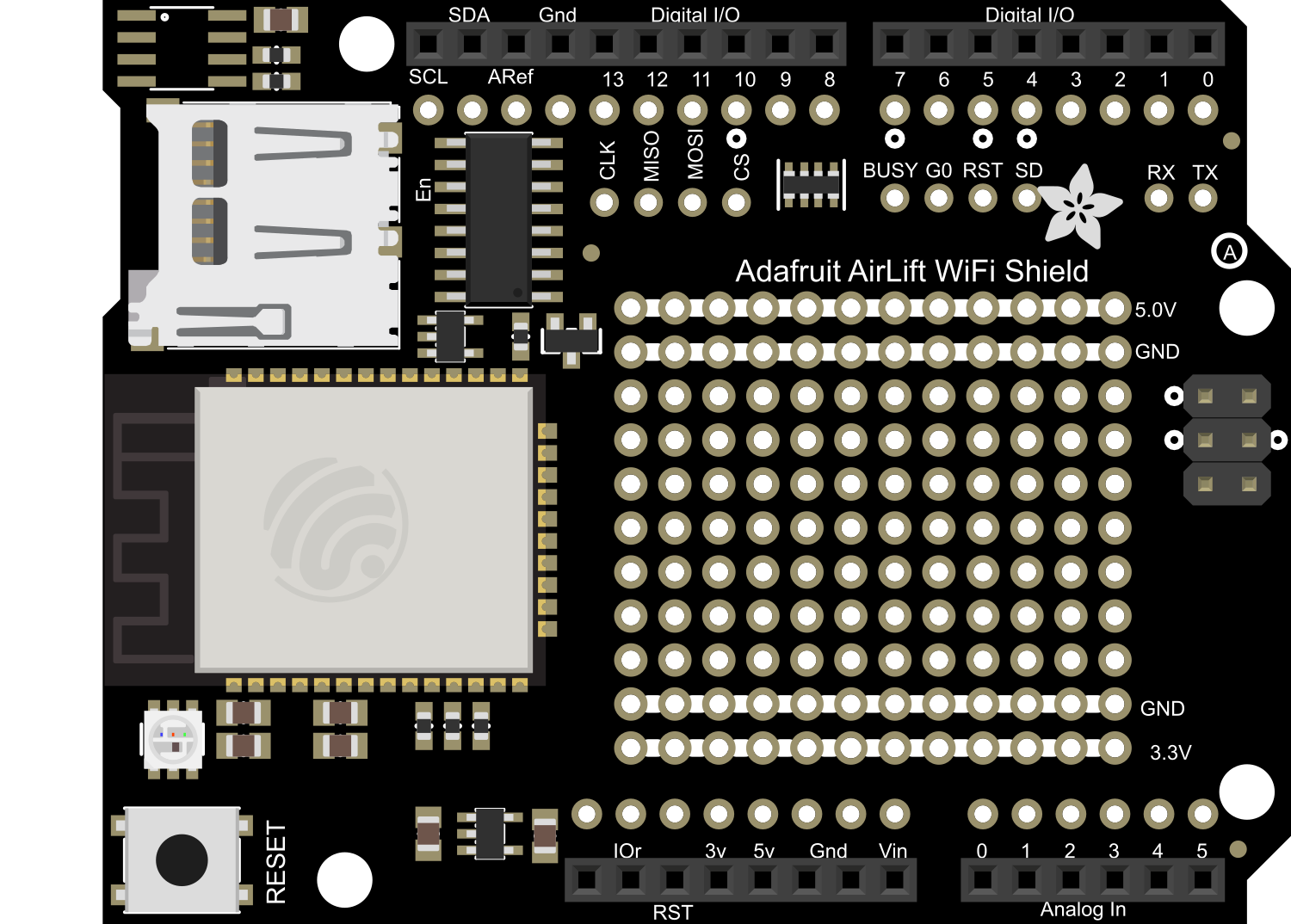
The Adafruit Airlift Shield is a powerful WiFi co-processor shield that leverages the capabilities of the ESP32 chipset to provide wireless connectivity for Arduino-based projects. This shield allows users to connect their Arduino to the internet, enabling a wide range of applications such as home automation, IoT devices, and remote sensor monitoring.
Explore Projects Built with Adafruit Airlift Shield
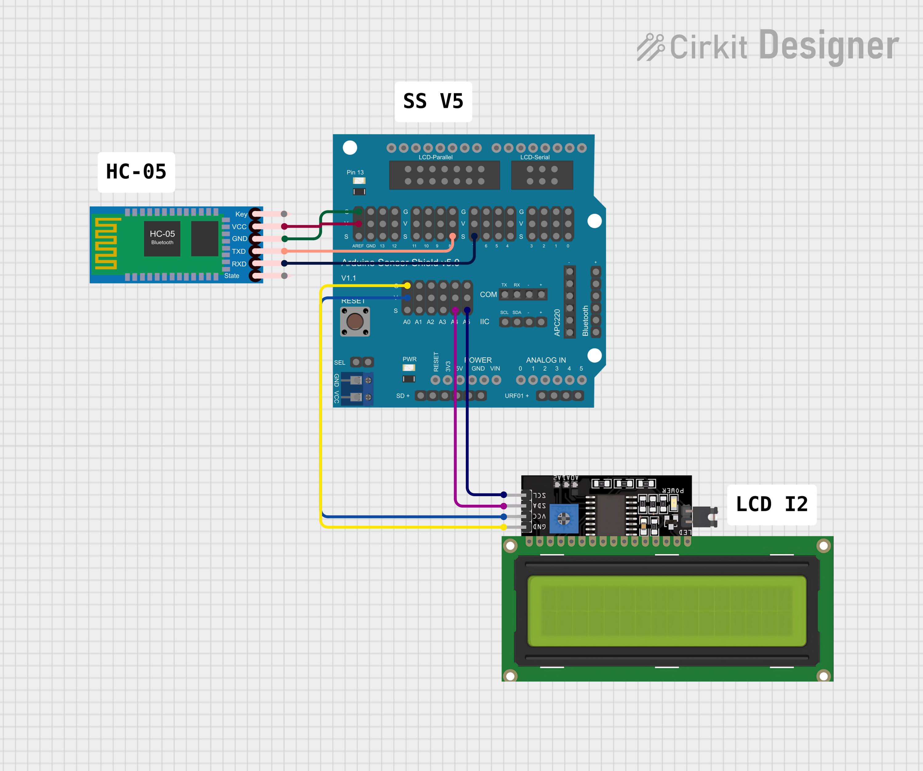
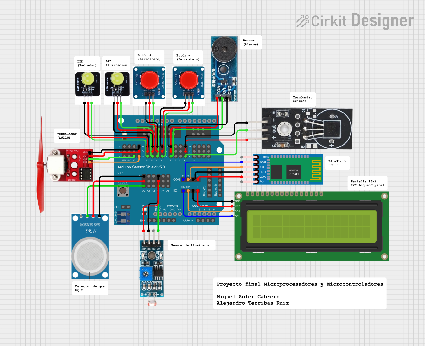
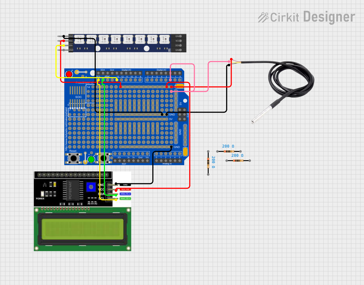
Explore Projects Built with Adafruit Airlift Shield
Common Applications and Use Cases
- Internet of Things (IoT) devices
- Home automation systems
- Remote data logging
- Wireless sensor networks
- Cloud-based applications
Technical Specifications
Key Technical Details
- Wireless Chipset: ESP32
- WiFi Standards: 802.11b/g/n
- Frequency Range: 2.4 GHz
- Integrated TCP/IP protocol stack
- Peak Current: 250mA
- Operating Voltage: 3.3V to 5V (Arduino compatible)
- Logic Level: 3.3V (5V tolerant on digital inputs)
Pin Configuration and Descriptions
| Pin Number | Function | Description |
|---|---|---|
| D0 | Reset | Resets the ESP32 module |
| D1 | GPIO0 | General-purpose I/O and programming mode select |
| D2 | GPIO2 | General-purpose I/O |
| D3 | GPIO15 | General-purpose I/O |
| D4 | GPIO16 | General-purpose I/O |
| D5 | SPI Clock | Clock for SPI communication |
| D6 | SPI MISO | Master In Slave Out for SPI communication |
| D7 | SPI MOSI | Master Out Slave In for SPI communication |
| D8 | SPI CS | Chip Select for SPI communication |
| A0 | Analog Input | Analog sensor input |
| VIN | Voltage Input | Input voltage for the shield |
| 3V3 | 3.3V Output | 3.3V power output from the shield |
| GND | Ground | Common ground for the circuit |
Usage Instructions
How to Use the Component in a Circuit
Mounting the Shield: Place the Adafruit Airlift Shield on top of an Arduino UNO, ensuring that all the pins are aligned and properly seated.
Power Supply: Connect the Arduino to a power source. The Airlift Shield will draw power from the Arduino board.
Programming: Use the Arduino IDE to program the Arduino board. Make sure to include the appropriate libraries for the ESP32 and WiFi functionality.
Connecting to WiFi: Use the WiFi library functions to connect to a wireless network. You will need to provide the SSID and password of the network.
Accessing Online Services: Once connected to WiFi, you can use various internet protocols like HTTP, MQTT, etc., to interact with web services or other devices.
Important Considerations and Best Practices
Power Requirements: Ensure that your Arduino board can supply enough current to the Airlift Shield, especially when transmitting data over WiFi.
Antenna: The Airlift Shield comes with a built-in antenna. For better range, an external antenna can be connected if needed.
Library Compatibility: Make sure to use the latest version of the Adafruit Airlift library and dependencies to ensure compatibility.
Firmware Updates: Keep the ESP32 firmware up to date to benefit from the latest features and security patches.
Troubleshooting and FAQs
Common Issues Users Might Face
WiFi Connection Issues: If the shield is not connecting to WiFi, ensure that the network credentials are correct and that the signal strength is adequate.
Serial Communication Errors: Check that the correct serial port is selected in the Arduino IDE and that the baud rate matches the one set in your code.
Power Issues: If the shield is unresponsive, verify that the Arduino board is supplying sufficient power.
Solutions and Tips for Troubleshooting
Reset the Shield: Press the reset button on the shield to reboot the ESP32 module.
Check Solder Joints: Ensure that all the header pins are soldered correctly and making good contact with the Arduino board.
Update Libraries and Firmware: Make sure that all libraries and the ESP32 firmware are up to date.
Serial Debugging: Use serial print statements to debug and track down issues in your code.
FAQs
Q: Can I use the Airlift Shield with other Arduino boards? A: Yes, the shield is compatible with any Arduino board that has the same form factor and voltage levels as the Arduino UNO.
Q: How do I update the ESP32 firmware? A: Follow the instructions provided by Adafruit for updating the firmware, which typically involves downloading the latest firmware and flashing it to the ESP32 using the Arduino IDE.
Q: Can I use external antennas with the Airlift Shield? A: Yes, the shield has a connector for an external antenna, which can be used to improve WiFi signal strength and range.
Example Code for Arduino UNO
#include <WiFi.h>
#include <SPI.h>

// Replace with your network credentials
const char* ssid = "your_SSID";
const char* password = "your_PASSWORD";

void setup() {
  // Initialize serial communication
  Serial.begin(115200);

  // Start the WiFi connection
  Serial.println("Connecting to WiFi...");
  WiFi.begin(ssid, password);

  while (WiFi.status() != WL_CONNECTED) {
    delay(500);
    Serial.print(".");
  }

  Serial.println("");
  Serial.println("WiFi connected.");
  Serial.print("IP address: ");
  Serial.println(WiFi.localIP());
}

void loop() {
  // Your code here to interact with the WiFi network
}
Remember to replace your_SSID and your_PASSWORD with your actual WiFi network credentials. This example will connect your Arduino to the WiFi network and print the IP address to the Serial Monitor.