How to Use ESP32-S3 WROOM2: Examples, Pinouts, and Specs
Introduction
The ESP32-S3 WROOM2 is a high-performance microcontroller module manufactured by Freenove (Part ID: ESP32). It is designed for Internet of Things (IoT) applications, offering integrated Wi-Fi and Bluetooth capabilities. Powered by a dual-core processor, this module provides robust performance for a wide range of applications, from smart home devices to industrial automation. Its ample GPIO pins and versatile connectivity options make it a popular choice for developers and hobbyists alike.
Explore Projects Built with ESP32-S3 WROOM2


Explore Projects Built with ESP32-S3 WROOM2
Common Applications
- IoT devices (e.g., smart home systems, wearables)
- Wireless sensor networks
- Robotics and automation
- Data logging and monitoring systems
- Prototyping and educational projects
Technical Specifications
The following table outlines the key technical details of the ESP32-S3 WROOM2 module:
| Parameter | Value |
|---|---|
| Processor | Dual-core Xtensa® LX7 @ 240 MHz |
| Wireless Connectivity | Wi-Fi 802.11 b/g/n (2.4 GHz), Bluetooth 5.0 LE |
| Flash Memory | 4 MB (expandable in some variants) |
| SRAM | 512 KB |
| GPIO Pins | 45 (including ADC, DAC, PWM, I2C, SPI, UART, etc.) |
| Operating Voltage | 3.3 V |
| Input Voltage Range | 3.0 V to 3.6 V |
| Power Consumption | Ultra-low power consumption in deep sleep mode (~10 µA) |
| Operating Temperature | -40°C to +85°C |
| Dimensions | 18 mm x 25.5 mm |
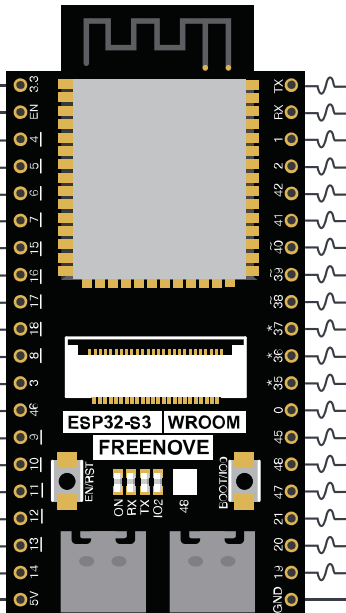
Pin Configuration
The ESP32-S3 WROOM2 module features a total of 45 GPIO pins, each with specific functions. Below is a summary of the pin configuration:
| Pin Name | Function | Description |
|---|---|---|
| GPIO0 | Boot Mode Selection | Used for flashing firmware; pulled low to enter bootloader mode. |
| GPIO1 | UART TX | Transmit pin for UART communication. |
| GPIO3 | UART RX | Receive pin for UART communication. |
| GPIO4 | General Purpose I/O, PWM | Can be used for digital I/O or PWM output. |
| GPIO12-15 | SPI Interface | SPI communication pins (MISO, MOSI, SCK, CS). |
| GPIO21 | I2C SDA | Data line for I2C communication. |
| GPIO22 | I2C SCL | Clock line for I2C communication. |
| GPIO25-26 | DAC Output | Digital-to-Analog Converter pins. |
| GPIO32-39 | ADC Input | Analog-to-Digital Converter pins. |
Note: Some GPIO pins have dual or special functions. Refer to the official datasheet for detailed pin multiplexing information.
Usage Instructions
How to Use the ESP32-S3 WROOM2 in a Circuit
- Power Supply: Ensure the module is powered with a stable 3.3 V supply. Avoid exceeding the input voltage range (3.0 V to 3.6 V) to prevent damage.
- Boot Mode: To flash firmware, connect GPIO0 to GND and reset the module. After flashing, disconnect GPIO0 from GND and reset again to boot normally.
- GPIO Usage: Connect peripherals (e.g., sensors, actuators) to the GPIO pins. Use appropriate pull-up or pull-down resistors if required.
- Programming: The ESP32-S3 WROOM2 can be programmed using the Arduino IDE, ESP-IDF, or other compatible environments.
Example: Connecting to an Arduino UNO
The ESP32-S3 WROOM2 can communicate with an Arduino UNO via UART. Below is an example of how to send data from the ESP32 to the Arduino:
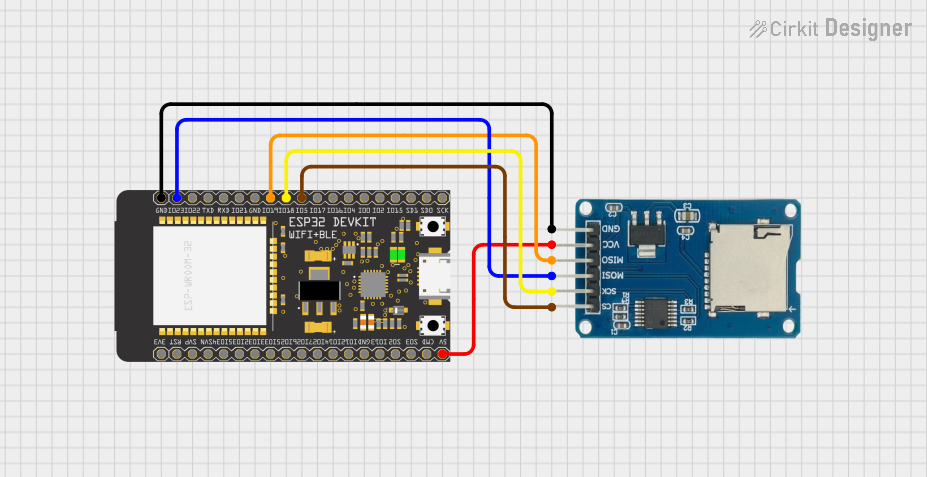
Wiring
- Connect ESP32 GPIO1 (TX) to Arduino RX.
- Connect ESP32 GPIO3 (RX) to Arduino TX.
- Connect GND of both devices.
Example Code for ESP32-S3 WROOM2
// Include the necessary library for serial communication
void setup() {
  Serial.begin(115200); // Initialize serial communication at 115200 baud
  delay(1000);          // Wait for the serial monitor to initialize
}

void loop() {
  Serial.println("Hello from ESP32-S3 WROOM2!"); // Send a message to Arduino
  delay(1000); // Wait for 1 second before sending the next message
}
Example Code for Arduino UNO
void setup() {
  Serial.begin(115200); // Initialize serial communication at 115200 baud
}

void loop() {
  if (Serial.available()) { // Check if data is available from ESP32
    String message = Serial.readString(); // Read the incoming message
    Serial.println("Received: " + message); // Print the received message
  }
}
Best Practices
- Use level shifters if interfacing with 5 V logic devices.
- Avoid using GPIO pins reserved for internal functions (e.g., GPIO6-11 for flash memory).
- Use decoupling capacitors near the power supply pins to reduce noise.
Troubleshooting and FAQs
Common Issues
Module Not Responding
- Cause: Incorrect power supply or wiring.
- Solution: Verify the power supply voltage (3.3 V) and check all connections.
Cannot Flash Firmware
- Cause: GPIO0 not pulled low during boot.
- Solution: Ensure GPIO0 is connected to GND before resetting the module.
Wi-Fi Connection Fails
- Cause: Incorrect SSID or password.
- Solution: Double-check the Wi-Fi credentials in your code.
Bluetooth Not Discoverable
- Cause: Bluetooth not initialized in the code.
- Solution: Ensure the Bluetooth stack is properly configured in your program.
FAQs
Can the ESP32-S3 WROOM2 operate on 5 V?
- No, the module operates at 3.3 V. Use a voltage regulator or level shifter for 5 V systems.
What is the maximum range of Wi-Fi?
- The Wi-Fi range is approximately 50 meters indoors and 200 meters outdoors, depending on the environment.
Can I use the ESP32-S3 WROOM2 with batteries?
- Yes, you can use a 3.7 V LiPo battery with a voltage regulator to provide a stable 3.3 V supply.
Is the module compatible with ESP-IDF?
- Yes, the ESP32-S3 WROOM2 is fully compatible with the ESP-IDF development framework.
By following this documentation, you can effectively integrate the ESP32-S3 WROOM2 into your projects and troubleshoot common issues with ease.