How to Use Motor: Examples, Pinouts, and Specs
Introduction
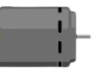
A motor is a device that converts electrical energy into mechanical energy. It is a fundamental component in countless applications, ranging from industrial machinery and robotics to household appliances and vehicles. Motors are available in various types, such as DC motors, AC motors, and stepper motors, each suited for specific tasks and performance requirements.
Explore Projects Built with Motor

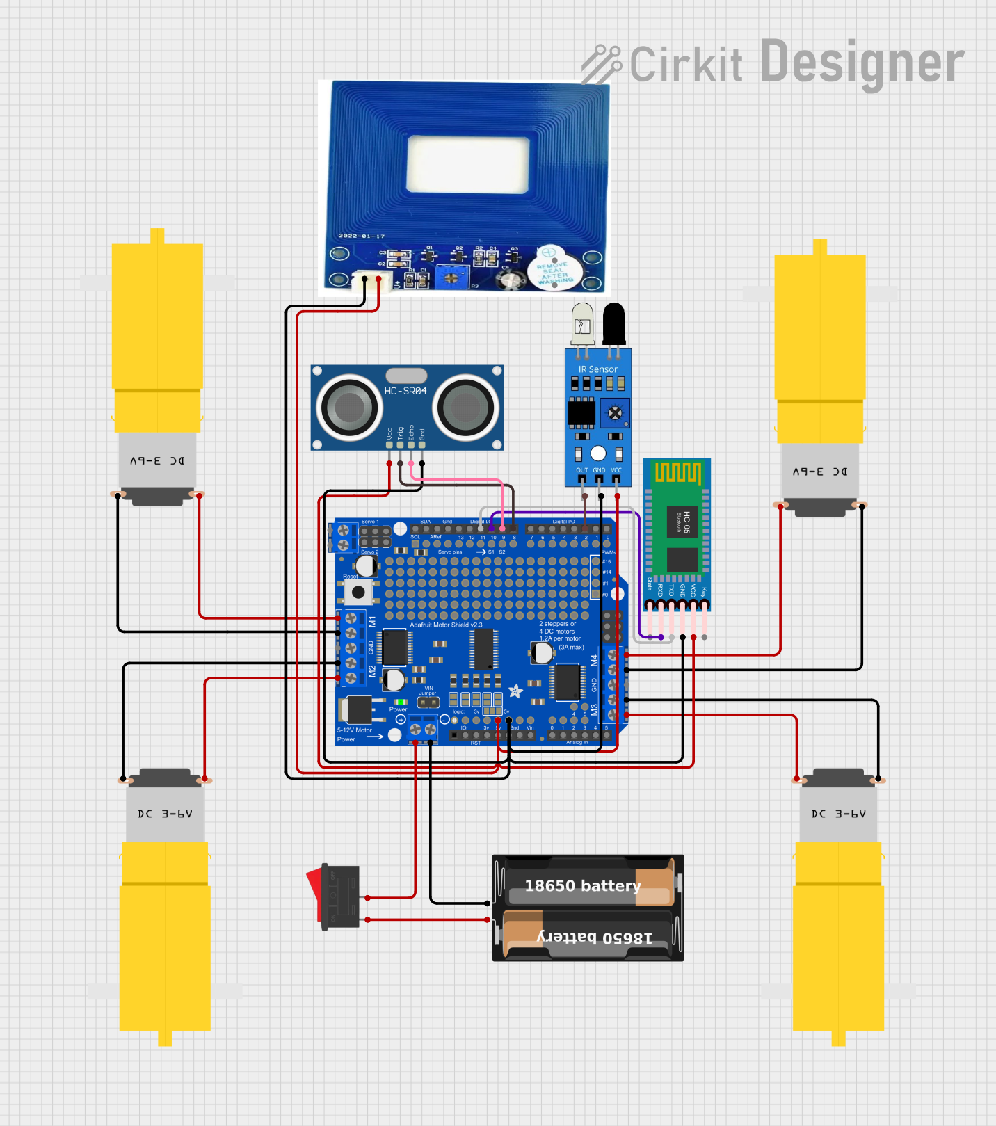
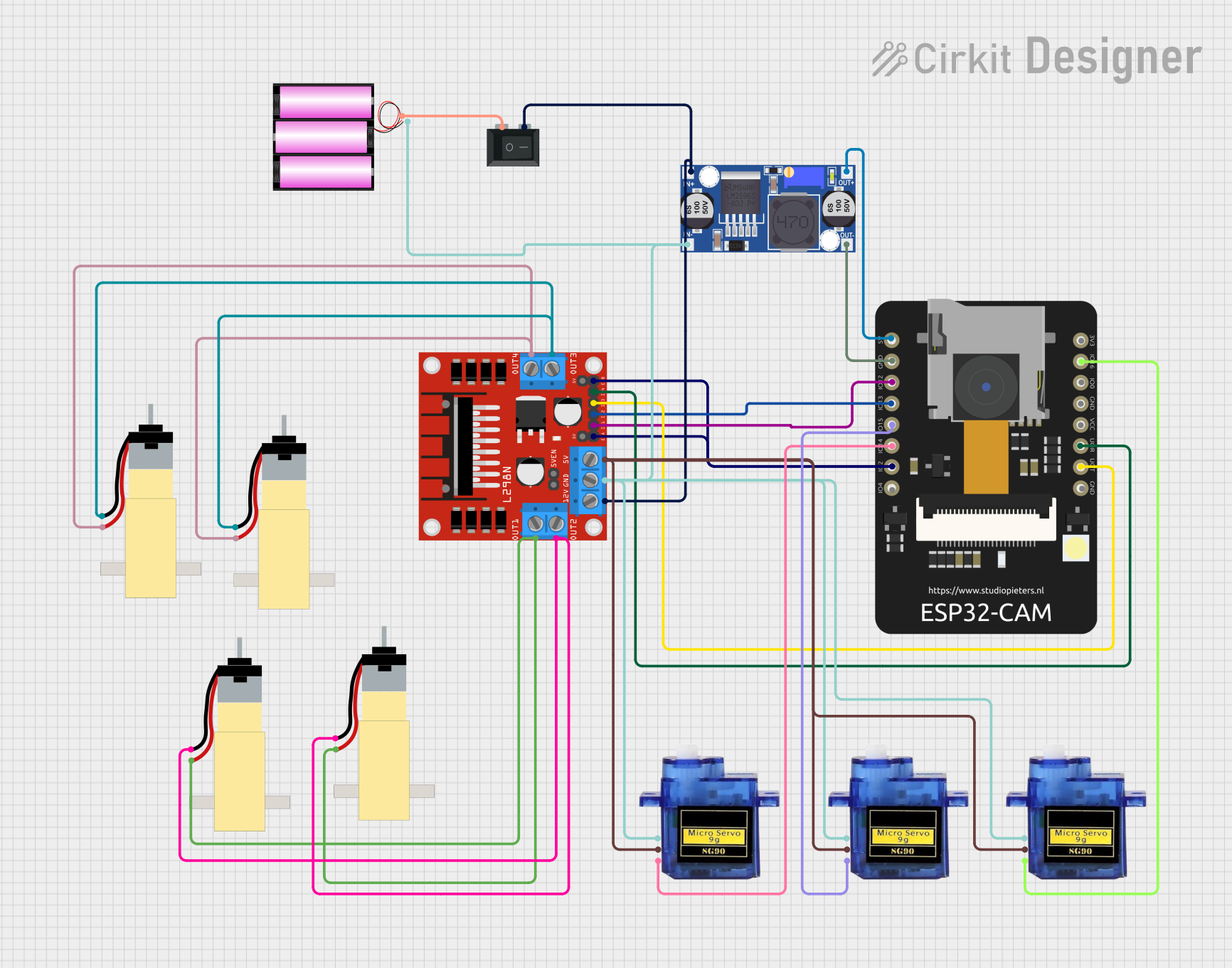
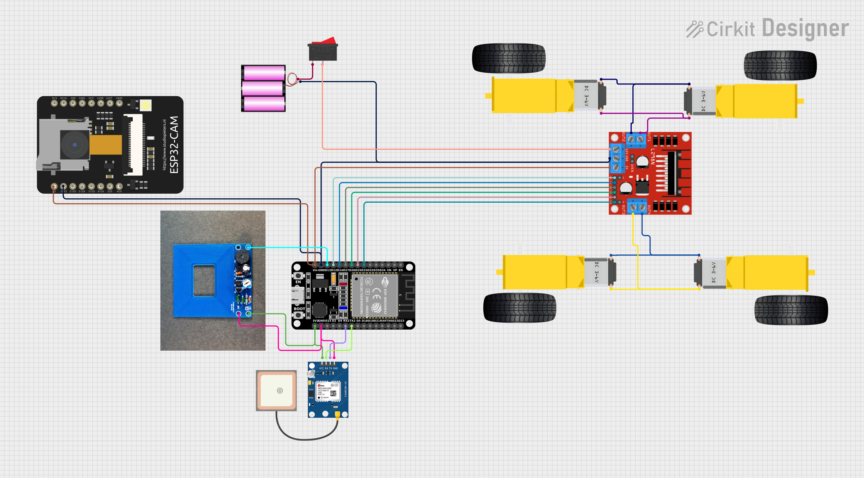
Explore Projects Built with Motor
Common Applications and Use Cases
- Robotics and automation systems
- Electric vehicles and drones
- Industrial machinery and conveyor belts
- Household appliances (e.g., fans, washing machines)
- Pumps and compressors
Technical Specifications
The specifications of a motor vary depending on its type and intended application. Below is an example of a DC motor's typical specifications:
| Parameter | Value |
|---|---|
| Operating Voltage | 6V - 12V |
| Rated Current | 0.5A - 2A |
| Stall Current | 2A - 5A |
| Rated Speed | 1000 - 5000 RPM |
| Torque | 0.1 - 1.5 Nm |
| Motor Type | Brushed DC Motor |
Pin Configuration and Descriptions
For a basic DC motor, the pin configuration is straightforward:
| Pin | Description |
|---|---|
| Pin 1 | Positive terminal (+) for power input |
| Pin 2 | Negative terminal (-) for power input |
For more advanced motors, such as stepper motors or brushless DC motors, additional pins may be present for control signals, feedback, or phase connections.
Usage Instructions
How to Use a Motor in a Circuit
- Power Supply: Ensure the motor is powered by a voltage source within its operating range. Exceeding the voltage rating can damage the motor.
- Motor Driver: Use a motor driver or H-bridge circuit to control the motor's speed and direction. Directly connecting a motor to a microcontroller is not recommended due to high current requirements.
- Connections:
- Connect the motor's positive terminal to the motor driver's output pin.
- Connect the motor's negative terminal to the motor driver's ground or output pin.
- Provide appropriate control signals to the motor driver from a microcontroller or other control system.
Important Considerations and Best Practices
- Current Limiting: Use a current-limiting resistor or a motor driver with built-in current protection to prevent overloading.
- Heat Dissipation: Motors can generate heat during operation. Ensure proper ventilation or heat sinks if necessary.
- Noise Suppression: Add capacitors across the motor terminals to reduce electrical noise and protect other components in the circuit.
- Load Matching: Select a motor with appropriate torque and speed characteristics for your application.
Example: Controlling a DC Motor with Arduino UNO
Below is an example of how to control a DC motor using an Arduino UNO and an L298N motor driver:
// Example: Controlling a DC Motor with Arduino UNO
// Connect the motor to the L298N motor driver
// IN1 and IN2 are control pins for the motor

const int IN1 = 9; // Connect to IN1 on the motor driver
const int IN2 = 10; // Connect to IN2 on the motor driver
const int ENA = 5; // Connect to ENA (PWM pin) on the motor driver

void setup() {
  pinMode(IN1, OUTPUT); // Set IN1 as output
  pinMode(IN2, OUTPUT); // Set IN2 as output
  pinMode(ENA, OUTPUT); // Set ENA as output
}

void loop() {
  // Rotate motor forward
  digitalWrite(IN1, HIGH); // Set IN1 high
  digitalWrite(IN2, LOW);  // Set IN2 low
  analogWrite(ENA, 128);   // Set speed (0-255)

  delay(2000); // Run motor for 2 seconds

  // Rotate motor backward
  digitalWrite(IN1, LOW);  // Set IN1 low
  digitalWrite(IN2, HIGH); // Set IN2 high
  analogWrite(ENA, 128);   // Set speed (0-255)

  delay(2000); // Run motor for 2 seconds

  // Stop motor
  digitalWrite(IN1, LOW);  // Set IN1 low
  digitalWrite(IN2, LOW);  // Set IN2 low
  analogWrite(ENA, 0);     // Set speed to 0

  delay(2000); // Wait for 2 seconds
}
Troubleshooting and FAQs
Common Issues and Solutions
Motor Does Not Spin:
- Check the power supply voltage and current. Ensure it meets the motor's requirements.
- Verify the connections between the motor, motor driver, and power source.
- Ensure the control signals from the microcontroller are correct.
Motor Spins in the Wrong Direction:
- Reverse the connections of the motor's terminals or adjust the control signals.
Motor Overheats:
- Reduce the load on the motor or ensure proper ventilation.
- Check for excessive current draw and use a current-limiting device if necessary.
Excessive Noise or Vibration:
- Add capacitors across the motor terminals to suppress electrical noise.
- Inspect the motor for mechanical issues, such as misalignment or worn bearings.
FAQs
Q: Can I connect a motor directly to an Arduino?
A: No, motors typically require more current than an Arduino can supply. Use a motor driver or H-bridge circuit to safely control the motor.
Q: How do I choose the right motor for my project?
A: Consider the required torque, speed, voltage, and current ratings. Match these parameters to your application's needs.
Q: What is the purpose of a motor driver?
A: A motor driver acts as an interface between the motor and the control system, allowing you to control the motor's speed and direction safely.