Cirkit Designer
Your all-in-one circuit design IDE
Home /
Component Documentation
How to Use Adafruit Trinket 3V: Examples, Pinouts, and Specs
Introduction
The Adafruit Trinket 3V is a compact and versatile microcontroller board that harnesses the capabilities of the ATtiny85 microcontroller. Designed for hobbyists and professionals alike, the Trinket 3V offers a cost-effective platform for projects where space is at a premium and power consumption is a concern. Its small size makes it ideal for wearables, portable projects, and Internet of Things (IoT) devices.
Explore Projects Built with Adafruit Trinket 3V
Battery-Powered Gas Sensor and Servo Control with Adafruit Trinket M0
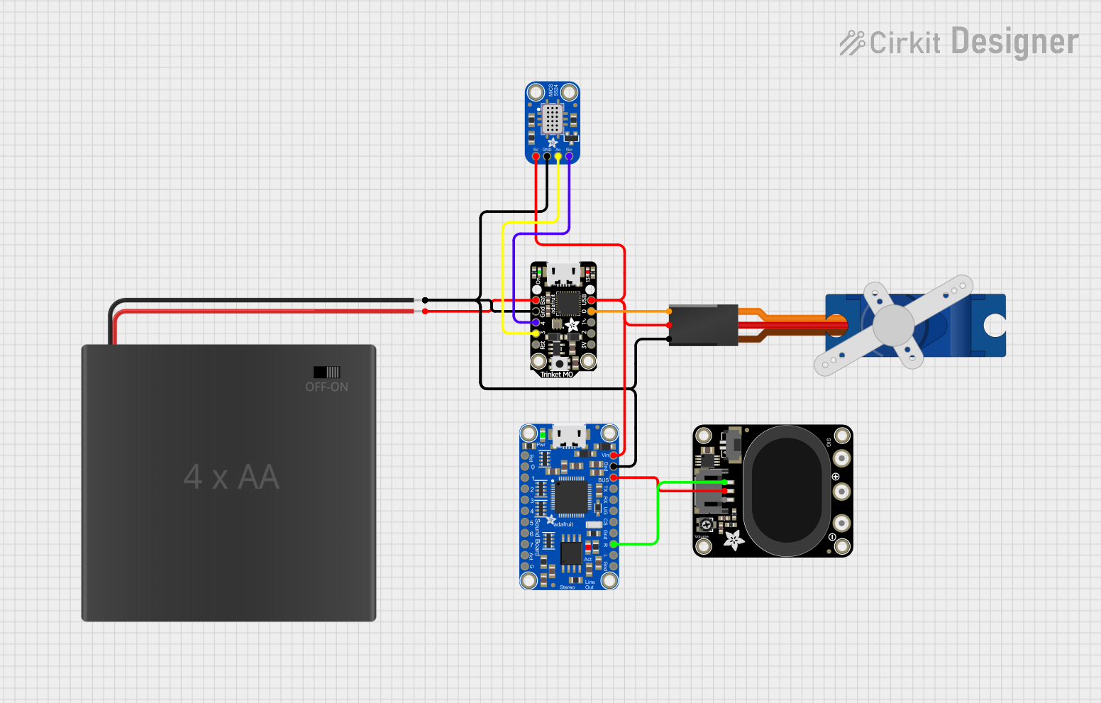
This circuit is a sensor-based system that uses an Adafruit Trinket M0 microcontroller to read data from a MiCS-5524 gas sensor and control a Tower Pro SG90 servo motor. Additionally, it includes an Adafruit Audio FX Mini Sound Board connected to a STEMMA speaker for audio output, all powered by a 4xAA battery pack.
Battery-Powered Smart Light with Proximity Sensor and OLED Display using Adafruit QT Py RP2040

This circuit is a portable, battery-powered system featuring an Adafruit QT Py RP2040 microcontroller that interfaces with an OLED display, a proximity sensor, an accelerometer, and an RGB LED strip. The system is powered by a lithium-ion battery with a step-up boost converter to provide 5V for the LED strip, and it includes a toggle switch for power control. The microcontroller communicates with the sensors and display via I2C.
NodeMCU ESP8266 Controlled Drone with TFT Display and nRF24L01 Communication
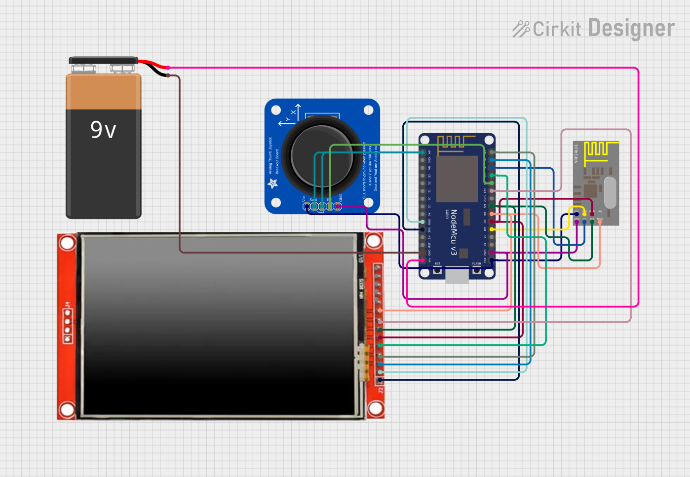
This circuit features a NodeMCU V3 ESP8266 microcontroller interfaced with an LCD TFT screen, an nRF24L01 wireless transceiver, and an Adafruit Analog 2-Axis Joystick. The NodeMCU collects joystick inputs and displays information on the TFT screen, while also communicating with other devices via the nRF24L01 module. The circuit is powered by a 9V battery, with the NodeMCU regulating the voltage for other components.
Battery-Powered Smart Sensor Hub with Adafruit QT Py RP2040

This circuit features an Adafruit QT Py RP2040 microcontroller interfaced with an APDS9960 proximity sensor, an MPU6050 accelerometer and gyroscope, and an OLED display via I2C communication. It also includes a buzzer controlled by the microcontroller and is powered by a 3.7V LiPo battery with a toggle switch for power control.
Explore Projects Built with Adafruit Trinket 3V
Battery-Powered Gas Sensor and Servo Control with Adafruit Trinket M0
This circuit is a sensor-based system that uses an Adafruit Trinket M0 microcontroller to read data from a MiCS-5524 gas sensor and control a Tower Pro SG90 servo motor. Additionally, it includes an Adafruit Audio FX Mini Sound Board connected to a STEMMA speaker for audio output, all powered by a 4xAA battery pack.
Battery-Powered Smart Light with Proximity Sensor and OLED Display using Adafruit QT Py RP2040
This circuit is a portable, battery-powered system featuring an Adafruit QT Py RP2040 microcontroller that interfaces with an OLED display, a proximity sensor, an accelerometer, and an RGB LED strip. The system is powered by a lithium-ion battery with a step-up boost converter to provide 5V for the LED strip, and it includes a toggle switch for power control. The microcontroller communicates with the sensors and display via I2C.
NodeMCU ESP8266 Controlled Drone with TFT Display and nRF24L01 Communication
This circuit features a NodeMCU V3 ESP8266 microcontroller interfaced with an LCD TFT screen, an nRF24L01 wireless transceiver, and an Adafruit Analog 2-Axis Joystick. The NodeMCU collects joystick inputs and displays information on the TFT screen, while also communicating with other devices via the nRF24L01 module. The circuit is powered by a 9V battery, with the NodeMCU regulating the voltage for other components.
Battery-Powered Smart Sensor Hub with Adafruit QT Py RP2040
This circuit features an Adafruit QT Py RP2040 microcontroller interfaced with an APDS9960 proximity sensor, an MPU6050 accelerometer and gyroscope, and an OLED display via I2C communication. It also includes a buzzer controlled by the microcontroller and is powered by a 3.7V LiPo battery with a toggle switch for power control.
Common Applications and Use Cases
- Wearable electronics
- Small robotics projects
- USB peripheral development
- Prototyping IoT devices
- Educational purposes for learning electronics and programming
Technical Specifications
Key Technical Details
- Microcontroller: ATtiny85
- Operating Voltage: 3.3V
- Input Voltage: 3.5V to 16V (via BAT+ pin)
- Digital I/O Pins: 5 (of which 2 are used for USB if the USB interface is enabled)
- PWM Channels: 3
- Analog Input Channels: 4
- Flash Memory: 8 KB (ATtiny85) with 2.75 KB used by bootloader
- SRAM: 512 bytes
- EEPROM: 512 bytes
- Clock Speed: 8 MHz
- Dimensions: 15.5mm x 31mm x 5mm
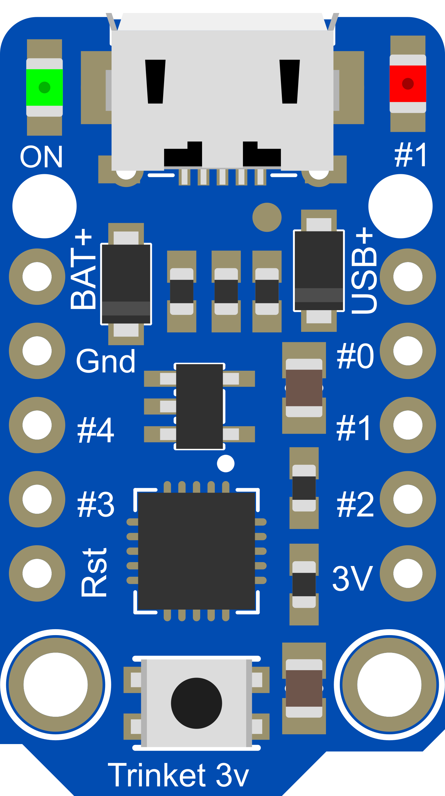
Pin Configuration and Descriptions
| Pin # | Name | Description |
|---|---|---|
| 1 | BAT+ | Battery input for an external power supply (3.5V to 16V) |
| 2 | GND | Ground pin |
| 3 | 5V | Regulated output used to power external components |
| 4 | #0 | GPIO pin, also used for USB data- if USB is enabled |
| 5 | #1 | GPIO pin, also used for USB data+ if USB is enabled |
| 6 | #2 | GPIO pin, can also function as an analog input (A1) |
| 7 | #3 | GPIO pin, can also function as an analog input (A3) and PWM output |
| 8 | #4 | GPIO pin, can also function as an analog input (A2) and PWM output |
| 9 | RESET | Reset pin (active low) |
Usage Instructions
How to Use the Component in a Circuit
- Powering the Trinket: Connect a battery or power supply to the BAT+ and GND pins, ensuring the voltage is within the 3.5V to 16V range.
- Connecting I/O: Attach sensors, actuators, or other peripherals to the GPIO pins as required by your project.
- Programming: Use the USB connection to program the Trinket with the Arduino IDE or other compatible software.
Important Considerations and Best Practices
- Always ensure that the power supply voltage does not exceed the recommended range to prevent damage.
- When using PWM outputs, ensure that the connected devices are compatible with the 3.3V logic level.
- To minimize noise and power consumption, avoid using unnecessary pull-up or pull-down resistors if possible.
- Use capacitors for power supply decoupling to reduce voltage spikes and noise.
- Remember that using the USB interface for programming will consume two digital I/O pins (#0 and #1).
Troubleshooting and FAQs
Common Issues Users Might Face
- Trinket not recognized by the computer: Ensure that the USB cable is properly connected and that the Trinket's bootloader is functioning correctly.
- Incorrect voltages at I/O pins: Verify that the power supply is within the specified range and that there are no shorts or open circuits.
- Inability to upload sketches: Check the selected board and port in the Arduino IDE, and ensure that the correct driver is installed.
Solutions and Tips for Troubleshooting
- If the Trinket is not recognized, try using a different USB cable or port, and double-check the soldering of the USB connector.
- For voltage issues, use a multimeter to check the power supply and the voltage at the I/O pins.
- When having trouble uploading sketches, consult the Adafruit guide for setting up the Arduino IDE with the Trinket.
Example Code for Arduino UNO
// Blink an LED connected to pin #2 on the Adafruit Trinket 3V

#define LED_PIN 2

void setup() {
  // Set the LED pin as an output
  pinMode(LED_PIN, OUTPUT);
}

void loop() {
  // Turn the LED on
  digitalWrite(LED_PIN, HIGH);
  delay(1000); // Wait for 1 second
  // Turn the LED off
  digitalWrite(LED_PIN, LOW);
  delay(1000); // Wait for 1 second
}
Note: This code is for demonstration purposes and assumes that an LED with an appropriate current-limiting resistor is connected to pin #2 of the Trinket 3V.
For further assistance, refer to the Adafruit Trinket 3V forums and the extensive online resources available for troubleshooting and project ideas.