
How to Use ISOLATOR SWITCH: Examples, Pinouts, and Specs
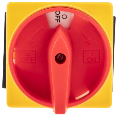
 Design with ISOLATOR SWITCH in Cirkit Designer
Introduction
An isolator switch is a mechanical switch designed to ensure that an electrical circuit is completely de-energized for maintenance or safety purposes. It provides a visible break in the circuit, making it an essential component in electrical systems where safety and reliability are critical. Isolator switches are commonly used in high-voltage applications, industrial power systems, and electrical substations.
Explore Projects Built with ISOLATOR SWITCH
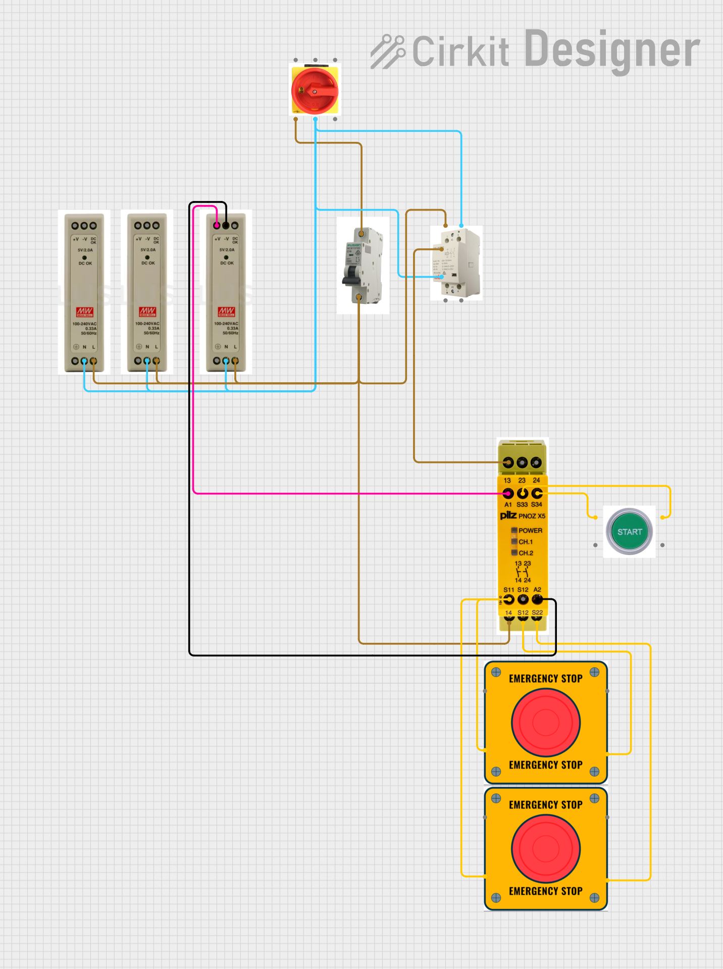 Open Project in Cirkit Designer
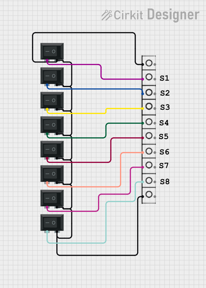 Open Project in Cirkit Designer
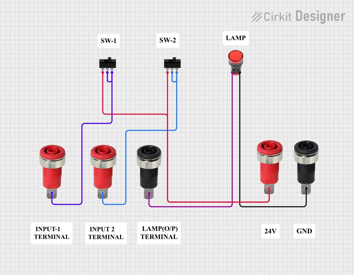 Open Project in Cirkit Designer
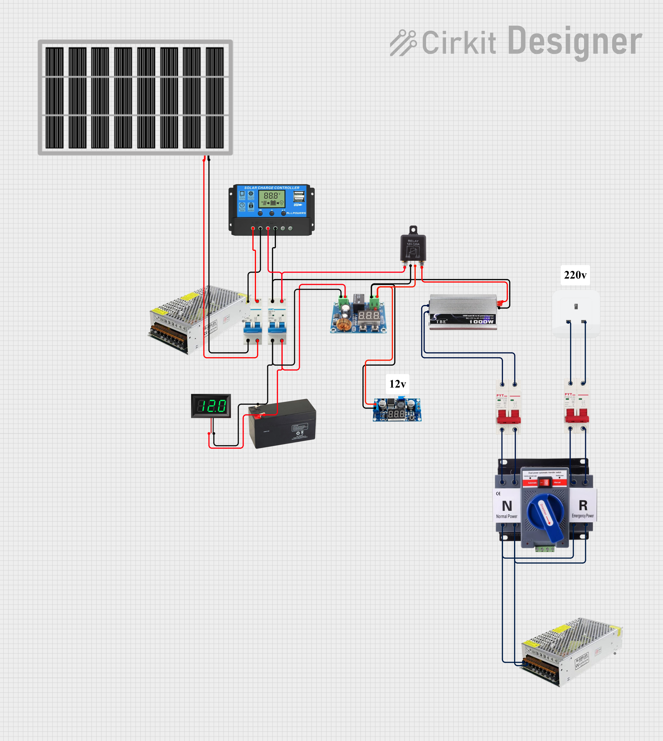 Open Project in Cirkit Designer
Explore Projects Built with ISOLATOR SWITCH
Open Project in Cirkit DesignerOpen Project in Cirkit DesignerOpen Project in Cirkit DesignerOpen Project in Cirkit DesignerCommon Applications and Use Cases
- Electrical substations for isolating high-voltage equipment.
- Industrial machinery to ensure safe maintenance procedures.
- Solar power systems to disconnect panels during servicing.
- Residential and commercial electrical systems for emergency isolation.
- Power distribution systems to isolate faulty sections.
Technical Specifications
Below are the key technical details for the ISOLATOR SWITCH:
| Parameter | Value |
|---|---|
| Manufacturer | ISOLATOR SWITCH |
| Manufacturer Part ID | ISOLATOR SWITCH |
| Rated Voltage | Up to 36 kV (varies by model) |
| Rated Current | 10 A to 3150 A (varies by model) |
| Insulation Resistance | ≥ 10 MΩ |
| Operating Temperature | -25°C to +70°C |
| Mechanical Endurance | 10,000 operations |
| Mounting Type | Panel-mounted or wall-mounted |
| Contact Material | Copper or silver-plated copper |
| Enclosure Protection | IP20 to IP65 (depending on model) |
Pin Configuration and Descriptions
Isolator switches do not have traditional "pins" like electronic components but instead feature terminals for electrical connections. Below is a general description of the terminal configuration:
| Terminal | Description |
|---|---|
| Line Input | Connects to the incoming power supply. |
| Line Output | Connects to the load or downstream circuit. |
| Ground | Provides grounding for safety and fault protection. |
Usage Instructions
How to Use the ISOLATOR SWITCH in a Circuit
- Selection: Choose an isolator switch rated for the voltage and current of your application.
- Installation:
- Mount the switch securely on a panel or wall.
- Ensure proper alignment of terminals for easy wiring.
- Wiring:
- Connect the incoming power supply to the Line Input terminal.
- Connect the load or downstream circuit to the Line Output terminal.
- Attach the Ground terminal to the system ground for safety.
- Operation:
- Turn the switch to the "ON" position to energize the circuit.
- Turn the switch to the "OFF" position to de-energize the circuit for maintenance or safety.
Important Considerations and Best Practices
- Always verify that the isolator switch is in the "OFF" position before performing maintenance.
- Use appropriate wire gauges and connectors to handle the rated current.
- Ensure the enclosure rating (e.g., IP65) matches the environmental conditions of the installation site.
- Periodically inspect the switch for wear, corrosion, or loose connections.
- For high-voltage applications, ensure proper clearance and insulation to prevent arcing.
Arduino UNO Integration
While isolator switches are not typically used directly with microcontrollers like the Arduino UNO, they can be part of a larger system where the Arduino controls relays or contactors. Below is an example of how an Arduino can control a relay to operate an isolator switch indirectly:
// Arduino code to control a relay for operating an isolator switch
const int relayPin = 7; // Pin connected to the relay module

void setup() {
  pinMode(relayPin, OUTPUT); // Set relay pin as output
  digitalWrite(relayPin, LOW); // Ensure relay is off at startup
}

void loop() {
  // Turn on the relay (simulate closing the isolator switch)
  digitalWrite(relayPin, HIGH);
  delay(5000); // Keep the relay on for 5 seconds

  // Turn off the relay (simulate opening the isolator switch)
  digitalWrite(relayPin, LOW);
  delay(5000); // Keep the relay off for 5 seconds
}
Note: Ensure the relay module is rated for the voltage and current of the isolator switch.
Troubleshooting and FAQs
Common Issues Users Might Face
Switch Fails to Operate:
- Cause: Mechanical wear or internal damage.
- Solution: Inspect the switch for visible damage and replace if necessary.
Arcing During Operation:
- Cause: High voltage or current exceeding the switch's rating.
- Solution: Verify the switch's ratings and ensure proper load matching.
Loose Connections:
- Cause: Improper wiring or terminal screws not tightened.
- Solution: Check all connections and tighten terminal screws securely.
Corrosion or Rust:
- Cause: Exposure to moisture or harsh environments.
- Solution: Use a switch with an appropriate IP rating and consider additional protective measures.
Solutions and Tips for Troubleshooting
- Always de-energize the circuit before inspecting or troubleshooting the isolator switch.
- Use a multimeter to verify continuity and ensure the switch is functioning correctly.
- For high-voltage systems, consult a qualified electrician or technician for troubleshooting and repairs.
- Regularly maintain the switch by cleaning contacts and checking for mechanical wear.
By following this documentation, users can safely and effectively integrate the ISOLATOR SWITCH into their electrical systems.