How to Use Heatbed 310x310 24V: Examples, Pinouts, and Specs
Introduction
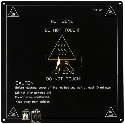
The Heatbed 310x310 24V is a heated platform designed for 3D printers, providing a consistent and evenly distributed heat source. This component enhances the adhesion of printed materials to the print surface, reducing warping and improving print quality. Its 310x310 mm size makes it suitable for medium to large 3D printers, and its 24V operation ensures efficient heating with reduced power loss.
Explore Projects Built with Heatbed 310x310 24V
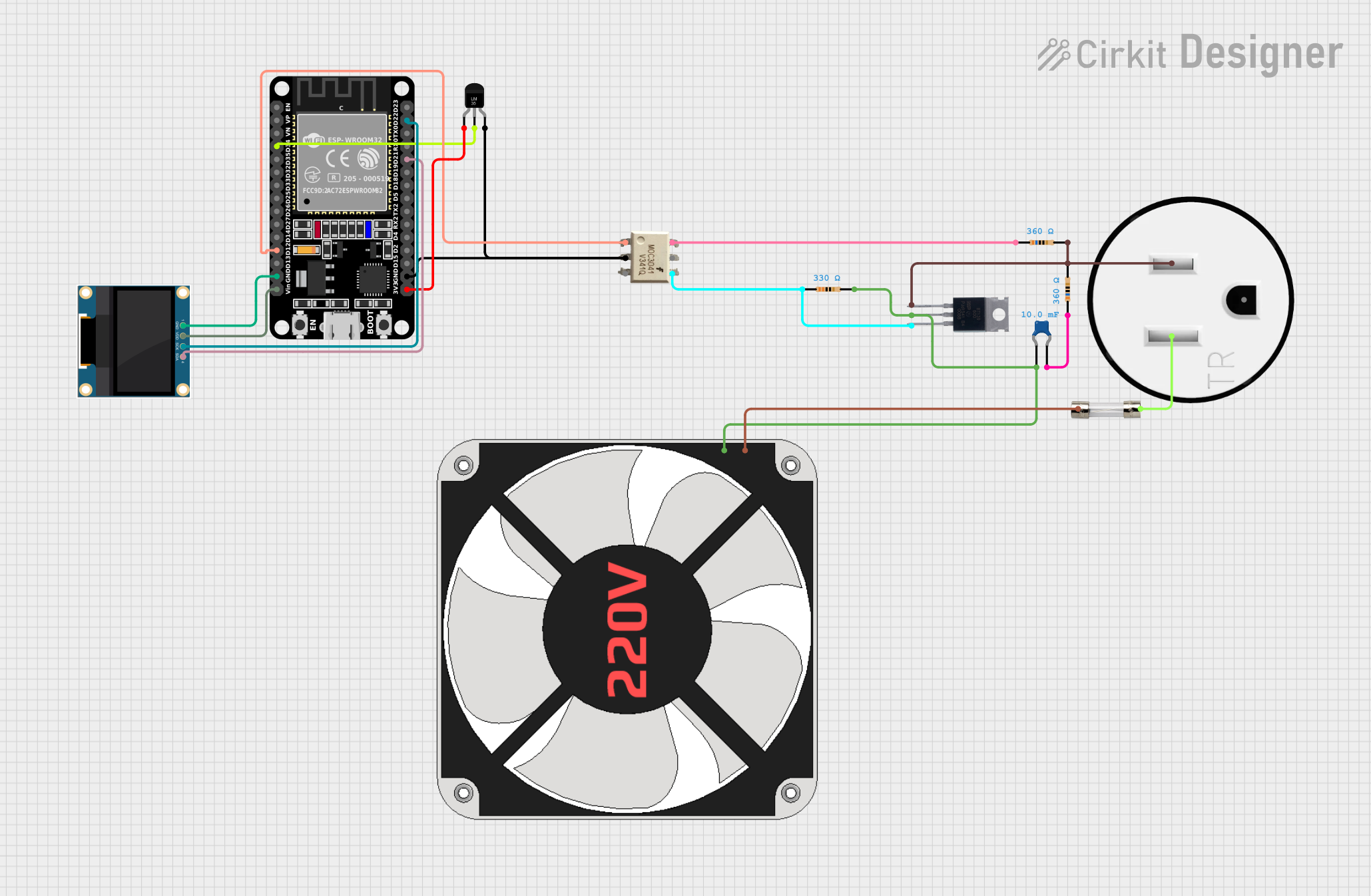
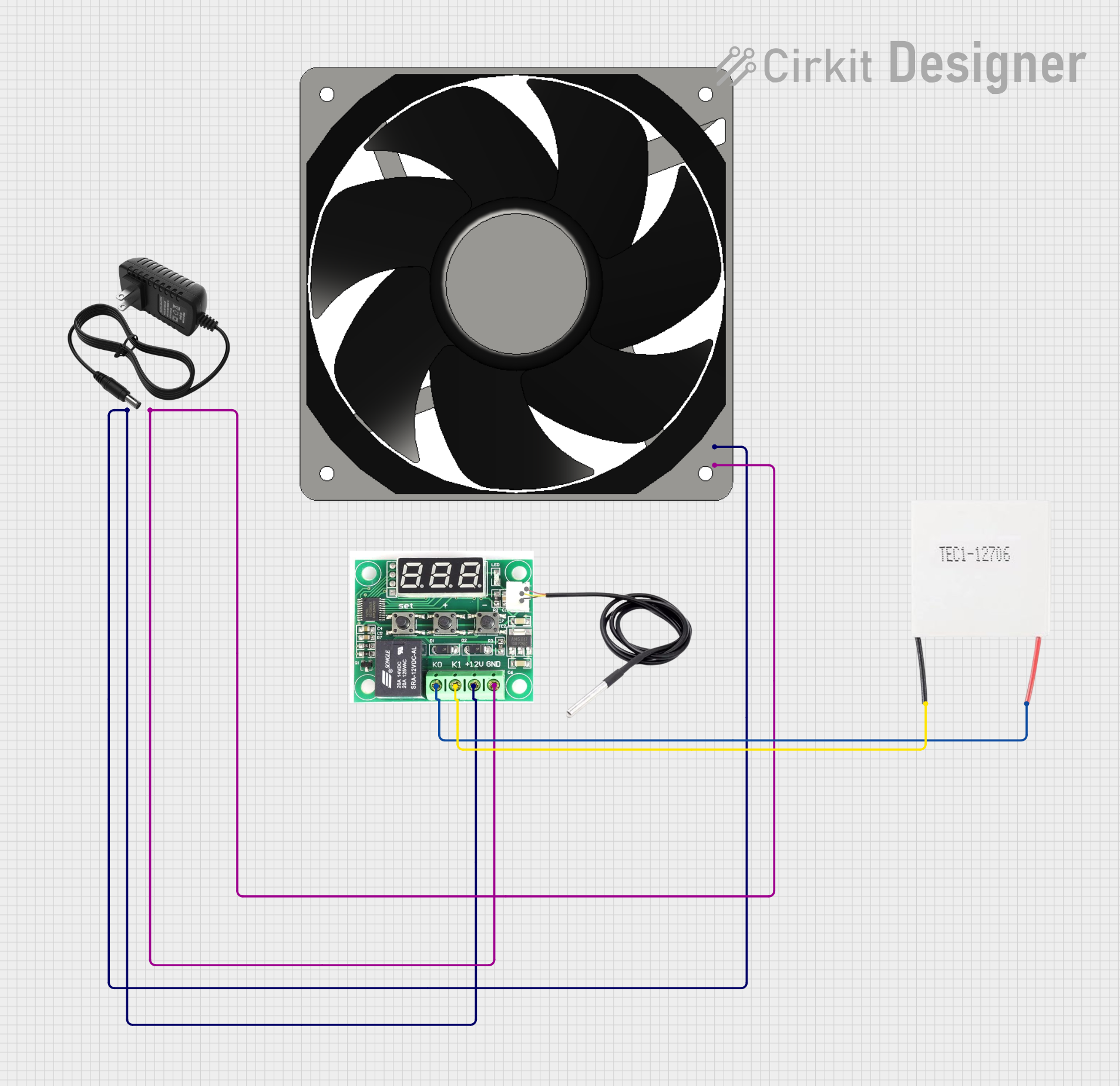


Explore Projects Built with Heatbed 310x310 24V
Common Applications and Use Cases
- 3D printing platforms for FDM (Fused Deposition Modeling) printers
- Printing with materials prone to warping, such as ABS, PETG, and Nylon
- Maintaining consistent bed temperatures for high-quality prints
- Retrofitting or upgrading 3D printers with larger or more efficient heatbeds
Technical Specifications
Below are the key technical details and pin configuration for the Heatbed 310x310 24V:
Key Technical Details
| Parameter | Specification |
|---|---|
| Dimensions | 310 mm x 310 mm |
| Operating Voltage | 24V DC |
| Power Rating | 200W - 250W (typical) |
| Heating Element Type | Embedded resistive heating trace |
| Surface Material | Aluminum or PCB (varies by model) |
| Temperature Range | Up to 120°C (recommended max) |
| Thermistor Type | NTC 100K (B3950) |
| Connector Type | Solder pads or terminal block |
Pin Configuration and Descriptions
| Pin/Pad Name | Description |
|---|---|
| + (Positive) | Connect to the 24V DC power supply (VCC). |
| - (Negative) | Connect to the ground (GND) of the power supply. |
| T1 | Thermistor lead 1 (connect to temperature sensor input). |
| T2 | Thermistor lead 2 (connect to temperature sensor input). |
Usage Instructions
How to Use the Heatbed in a Circuit
Power Connection:
- Connect the positive (+) pad to the 24V output of your power supply.
- Connect the negative (-) pad to the ground (GND) of your power supply.
- Ensure the power supply can handle the heatbed's power requirements (200W-250W).
Thermistor Connection:
- Connect the thermistor leads (T1 and T2) to the temperature sensor input of your 3D printer's control board.
- Most 3D printer controllers support NTC 100K thermistors by default.
Mounting:
- Secure the heatbed to the printer's frame using screws or clips.
- Use an insulating material (e.g., cork or silicone) beneath the heatbed to reduce heat loss.
Surface Preparation:
- Apply a print surface material (e.g., glass, PEI sheet, or adhesive tape) to the heatbed for better adhesion.
- Clean the surface regularly to remove debris or residue.
Temperature Control:
- Configure the desired bed temperature in your 3D printer's slicer software.
- Ensure the control board's firmware is calibrated for the thermistor type (NTC 100K).
Important Considerations and Best Practices
- Power Supply: Use a power supply rated for at least 20% more than the heatbed's maximum power consumption to ensure stable operation.
- Wiring: Use appropriately rated wires (e.g., 16 AWG or thicker) to handle the current without overheating.
- Safety: Avoid exceeding the recommended maximum temperature (120°C) to prevent damage to the heatbed or surrounding components.
- Leveling: Ensure the heatbed is level to avoid print failures or nozzle collisions.
- Firmware Settings: Verify that your 3D printer's firmware is configured for a 24V heatbed and the correct thermistor type.
Example Code for Arduino-Based 3D Printer Controller
Below is an example of configuring the heatbed in Marlin firmware for an Arduino-based 3D printer controller:
// Configuration for the heatbed thermistor in Marlin firmware
#define TEMP_SENSOR_BED 1  // Set to 1 for NTC 100K thermistor (B3950)

// Maximum temperature for the heatbed
#define BED_MAXTEMP 120    // Set the maximum allowable temperature for safety

// PID settings for heatbed temperature control
#define PIDTEMPBED         // Enable PID control for the heatbed
#define BED_PID_Kp 10.00   // Proportional gain
#define BED_PID_Ki 0.023   // Integral gain
#define BED_PID_Kd 305.4   // Derivative gain
Note: Always refer to your specific 3D printer's documentation for firmware configuration details.
Troubleshooting and FAQs
Common Issues and Solutions
Heatbed Not Heating:
- Cause: Loose or incorrect wiring.
- Solution: Verify all connections, ensuring the power supply and control board are properly connected.
Uneven Heating:
- Cause: Faulty heating element or poor insulation.
- Solution: Check for damage to the heatbed and ensure proper insulation beneath it.
Thermistor Reading Incorrect Temperature:
- Cause: Incorrect thermistor type configured in firmware.
- Solution: Update the firmware to match the thermistor type (e.g., NTC 100K).
Overheating:
- Cause: Faulty temperature control or incorrect firmware settings.
- Solution: Verify PID settings in the firmware and ensure the control board is functioning correctly.
Prints Not Sticking to the Bed:
- Cause: Dirty or unsuitable print surface.
- Solution: Clean the surface and use an appropriate adhesive or print surface material.
FAQs
Q1: Can I use this heatbed with a 12V power supply?
A1: No, this heatbed is designed for 24V operation. Using a 12V power supply will result in insufficient heating.
Q2: What is the recommended wire gauge for connecting the heatbed?
A2: Use 16 AWG or thicker wires to handle the current safely.
Q3: How do I know if the thermistor is working correctly?
A3: Check the temperature reading on your 3D printer's display. If it shows "0°C" or "def," the thermistor may be disconnected or faulty.
Q4: Can I use this heatbed with a glass print surface?
A4: Yes, a glass surface is compatible and provides a smooth, flat printing area. Ensure it is securely attached to the heatbed.
Q5: What is the maximum temperature this heatbed can reach?
A5: The recommended maximum temperature is 120°C to prevent damage to the heatbed or surrounding components.