How to Use DS1302 RTC: Examples, Pinouts, and Specs
Introduction
The DS1302 Real-Time Clock (RTC) is a low-power timekeeping device designed to maintain accurate time and date information. It communicates with microcontrollers using a simple serial interface and includes a battery backup feature, ensuring that timekeeping continues even during power outages. The DS1302 is widely used in applications requiring precise timekeeping, such as data loggers, alarm systems, and embedded systems.
Explore Projects Built with DS1302 RTC

Explore Projects Built with DS1302 RTC
Common Applications
- Digital clocks and timers
- Data logging systems
- Alarm and scheduling systems
- Home automation projects
- Microcontroller-based projects requiring time and date tracking
Technical Specifications
Key Technical Details
- Operating Voltage: 2.0V to 5.5V
- Current Consumption:
- 300 nA (typical) in battery backup mode
- 1.2 mA (typical) during active operation
- Timekeeping Accuracy: ±2 minutes per month at 25°C
- Communication Protocol: Serial (3-wire interface)
- Clock Features: Seconds, minutes, hours, day, date, month, year (with leap year compensation up to 2100)
- Battery Backup: Supports external battery for uninterrupted timekeeping
- Operating Temperature: -40°C to +85°C
- Package Type: 8-pin DIP or SOIC
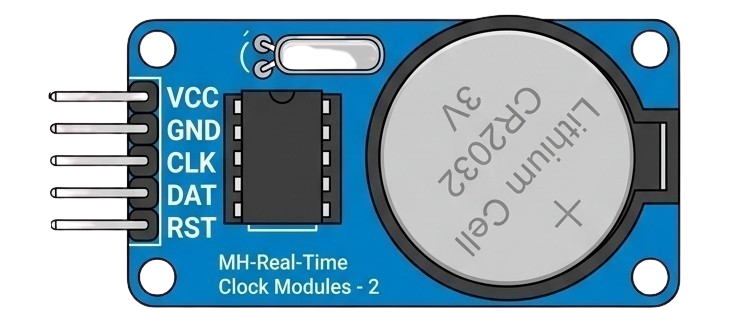
Pin Configuration and Descriptions
The DS1302 has 8 pins, as described in the table below:
| Pin Number | Pin Name | Description |
|---|---|---|
| 1 | VCC1 | Primary power supply (2.0V to 5.5V). |
| 2 | X1 | Oscillator input. Connect to a 32.768 kHz crystal. |
| 3 | X2 | Oscillator output. Connect to a 32.768 kHz crystal. |
| 4 | GND | Ground. |
| 5 | RST | Reset pin. Used to enable communication with the microcontroller. |
| 6 | I/O | Data input/output pin for serial communication. |
| 7 | SCLK | Serial clock input. Used to synchronize data transfer. |
| 8 | VCC2 | Backup power supply (e.g., a coin cell battery). Maintains time during outages. |
Usage Instructions
How to Use the DS1302 in a Circuit
- Power Supply: Connect the primary power supply (VCC1) to a regulated 3.3V or 5V source. Connect VCC2 to a coin cell battery (e.g., CR2032) for backup power.
- Crystal Oscillator: Attach a 32.768 kHz crystal between the X1 and X2 pins. No external capacitors are required.
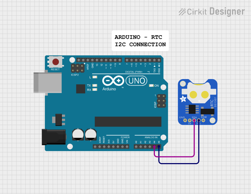
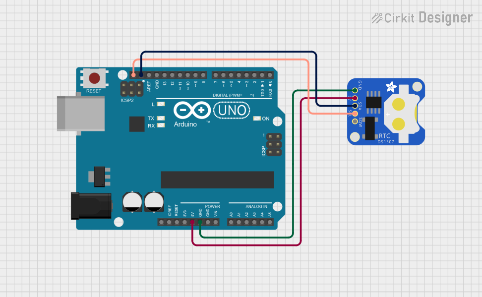
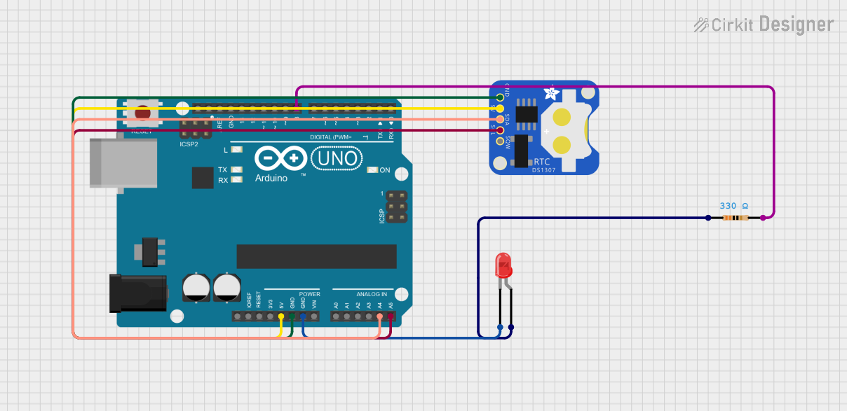
- Microcontroller Interface: Connect the RST, I/O, and SCLK pins to the corresponding GPIO pins on the Arduino UNO.
- Pull-Up Resistor: Use a 10kΩ pull-up resistor on the I/O line to ensure reliable communication.
- Software Library: Use the Arduino DS1302 library to simplify communication and time-setting tasks.
Important Considerations
- Ensure the backup battery is installed correctly to maintain timekeeping during power loss.
- Avoid using long wires for the crystal oscillator connections to minimize noise and ensure accuracy.
- Use decoupling capacitors (e.g., 0.1 µF) near the VCC1 pin to stabilize the power supply.
Example Arduino Code
Below is an example of how to interface the DS1302 with an Arduino UNO to read and set the time:
#include <DS1302.h>

// Define DS1302 pins connected to the Arduino
#define RST_PIN 7   // Reset pin connected to Arduino pin 7
#define IO_PIN 6    // I/O pin connected to Arduino pin 6
#define SCLK_PIN 5  // Serial clock pin connected to Arduino pin 5

// Create an instance of the DS1302 class
DS1302 rtc(RST_PIN, IO_PIN, SCLK_PIN);

void setup() {
  Serial.begin(9600); // Initialize serial communication for debugging

  // Set the current time and date (Year, Month, Day, Hour, Minute, Second)
  rtc.setTime(2023, 10, 15, 14, 30, 0); // Example: October 15, 2023, 14:30:00

  Serial.println("DS1302 RTC Initialized");
}

void loop() {
  // Read the current time from the DS1302
  Time t = rtc.getTime();

  // Print the time to the Serial Monitor
  Serial.print("Time: ");
  Serial.print(t.hour);
  Serial.print(":");
  Serial.print(t.min);
  Serial.print(":");
  Serial.println(t.sec);

  // Print the date to the Serial Monitor
  Serial.print("Date: ");
  Serial.print(t.date);
  Serial.print("/");
  Serial.print(t.mon);
  Serial.print("/");
  Serial.println(t.year);

  delay(1000); // Wait for 1 second before updating
}
Notes on the Code
- The
DS1302library must be installed in the Arduino IDE. You can install it via the Library Manager. - Modify the
rtc.setTime()function to set the desired initial time and date. - Ensure the pin definitions (
RST_PIN,IO_PIN,SCLK_PIN) match your circuit connections.
Troubleshooting and FAQs
Common Issues
Incorrect Time or Date
- Cause: The backup battery may be depleted, or the time was not set correctly.
- Solution: Replace the battery and use the
rtc.setTime()function to set the correct time.
No Communication with the DS1302
- Cause: Incorrect wiring or pin configuration.
- Solution: Double-check the connections between the DS1302 and the Arduino UNO. Ensure the RST, I/O, and SCLK pins are correctly connected.
Time Drift
- Cause: Poor-quality crystal oscillator or excessive noise on the oscillator pins.
- Solution: Use a high-quality 32.768 kHz crystal and keep the oscillator connections short.
Backup Battery Not Working
- Cause: Incorrect polarity or depleted battery.
- Solution: Verify the battery polarity and replace it if necessary.
FAQs
Q: Can the DS1302 handle daylight saving time (DST)?
A: No, the DS1302 does not have built-in support for DST. You must implement DST adjustments in your microcontroller code.
Q: What happens if both VCC1 and VCC2 are disconnected?
A: The DS1302 will lose its time and date information. Ensure at least one power source is always connected.
Q: Can I use the DS1302 with a 3.3V microcontroller?
A: Yes, the DS1302 operates within a voltage range of 2.0V to 5.5V, making it compatible with 3.3V systems.
Q: How long does the backup battery last?
A: A typical CR2032 coin cell battery can last several years, depending on the current consumption and battery quality.