Cirkit Designer Logo
Cirkit Designer
Your all-in-one circuit design IDE
Home / 
Component Documentation

How to Use FDC1004: Examples, Pinouts, and Specs

Image of FDC1004
Cirkit Designer LogoDesign with FDC1004 in Cirkit Designer

Introduction

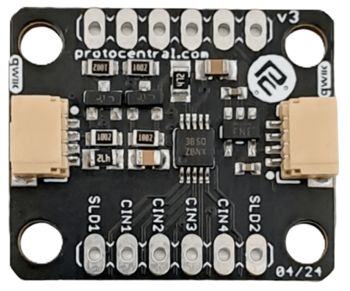
The FDC1004, manufactured by Protocentral (Part ID: FDC), is a high-precision capacitance-to-digital converter (CDC) designed to measure capacitance with exceptional accuracy and resolution. This component is ideal for applications requiring precise capacitive sensing, such as proximity sensing, liquid level sensing, and touch sensing. Its advanced features and ease of integration make it a popular choice for both industrial and consumer electronics.

Explore Projects Built with FDC1004

Use Cirkit Designer to design, explore, and prototype these projects online. Some projects support real-time simulation. Click "Open Project" to start designing instantly!
Battery-Powered Emergency Alert System with NUCLEO-F072RB, SIM800L, and GPS NEO 6M
Image of women safety: A project utilizing FDC1004 in a practical application
This circuit is an emergency alert system that uses a NUCLEO-F072RB microcontroller to send SMS alerts and make calls via a SIM800L GSM module, while obtaining location data from a GPS NEO 6M module. The system is powered by a Li-ion battery and includes a TP4056 module for battery charging and protection, with a rocker switch to control power to the microcontroller.
Cirkit Designer LogoOpen Project in Cirkit Designer
NFC-Enabled Access Control System with Time Logging
Image of doorlock: A project utilizing FDC1004 in a practical application
This circuit is designed for access control with time tracking capabilities. It features an NFC/RFID reader for authentication, an RTC module (DS3231) for real-time clock functionality, and an OLED display for user interaction. A 12V relay controls a magnetic lock, which is activated upon successful NFC/RFID authentication, and a button switch is likely used for manual operation or input. The T8_S3 microcontroller serves as the central processing unit, interfacing with the NFC/RFID reader, RTC, OLED, and relay to manage the access control logic.
Cirkit Designer LogoOpen Project in Cirkit Designer
NFC-Enabled Access Control System with Real-Time Clock and OLED Display
Image of doorlock: A project utilizing FDC1004 in a practical application
This circuit is designed as an access control system with time-tracking capabilities. It uses an NFC/RFID reader for authentication, a real-time clock for time-stamping events, and an OLED display for user interface, all controlled by a T8_S3 microcontroller. A relay module actuates a magnetic lock, and a button switch provides additional user input, with a switching power supply delivering the necessary voltages.
Cirkit Designer LogoOpen Project in Cirkit Designer
STM32 Nucleo F303RE Controlled Ultrasonic Sensing with RGB Feedback and I2C LCD Display
Image of CS435-final: A project utilizing FDC1004 in a practical application
This circuit features a STM32 Nucleo F303RE microcontroller interfaced with three HC-SR04 ultrasonic sensors for distance measurement and a 20x4 LCD display over I2C for data output. Additionally, there is a WS2812 RGB LED strip controlled by the microcontroller for visual feedback. The power supply provides a common 5V to the LCD, ultrasonic sensors, LED strip, and the microcontroller's +5V input, with all components sharing a common ground.
Cirkit Designer LogoOpen Project in Cirkit Designer

Explore Projects Built with FDC1004

Use Cirkit Designer to design, explore, and prototype these projects online. Some projects support real-time simulation. Click "Open Project" to start designing instantly!
Image of women safety: A project utilizing FDC1004 in a practical application
Battery-Powered Emergency Alert System with NUCLEO-F072RB, SIM800L, and GPS NEO 6M
This circuit is an emergency alert system that uses a NUCLEO-F072RB microcontroller to send SMS alerts and make calls via a SIM800L GSM module, while obtaining location data from a GPS NEO 6M module. The system is powered by a Li-ion battery and includes a TP4056 module for battery charging and protection, with a rocker switch to control power to the microcontroller.
Cirkit Designer LogoOpen Project in Cirkit Designer
Image of doorlock: A project utilizing FDC1004 in a practical application
NFC-Enabled Access Control System with Time Logging
This circuit is designed for access control with time tracking capabilities. It features an NFC/RFID reader for authentication, an RTC module (DS3231) for real-time clock functionality, and an OLED display for user interaction. A 12V relay controls a magnetic lock, which is activated upon successful NFC/RFID authentication, and a button switch is likely used for manual operation or input. The T8_S3 microcontroller serves as the central processing unit, interfacing with the NFC/RFID reader, RTC, OLED, and relay to manage the access control logic.
Cirkit Designer LogoOpen Project in Cirkit Designer
Image of doorlock: A project utilizing FDC1004 in a practical application
NFC-Enabled Access Control System with Real-Time Clock and OLED Display
This circuit is designed as an access control system with time-tracking capabilities. It uses an NFC/RFID reader for authentication, a real-time clock for time-stamping events, and an OLED display for user interface, all controlled by a T8_S3 microcontroller. A relay module actuates a magnetic lock, and a button switch provides additional user input, with a switching power supply delivering the necessary voltages.
Cirkit Designer LogoOpen Project in Cirkit Designer
Image of CS435-final: A project utilizing FDC1004 in a practical application
STM32 Nucleo F303RE Controlled Ultrasonic Sensing with RGB Feedback and I2C LCD Display
This circuit features a STM32 Nucleo F303RE microcontroller interfaced with three HC-SR04 ultrasonic sensors for distance measurement and a 20x4 LCD display over I2C for data output. Additionally, there is a WS2812 RGB LED strip controlled by the microcontroller for visual feedback. The power supply provides a common 5V to the LCD, ultrasonic sensors, LED strip, and the microcontroller's +5V input, with all components sharing a common ground.
Cirkit Designer LogoOpen Project in Cirkit Designer

Common Applications

  • Proximity Sensing: Detecting the presence or movement of objects.
  • Liquid Level Sensing: Measuring liquid levels in tanks or containers.
  • Touch Sensing: Implementing touch-sensitive interfaces for devices.
  • Environmental Monitoring: Measuring changes in capacitance due to environmental factors.

Technical Specifications

The FDC1004 offers robust performance and flexibility for capacitive sensing applications. Below are its key technical details:

Key Features

  • Supply Voltage: 3.3V to 5.5V
  • Capacitance Measurement Range: ±15 pF (programmable offset up to ±100 pF)
  • Resolution: 16-bit
  • Interface: I²C (Inter-Integrated Circuit)
  • Operating Temperature Range: -40°C to +85°C
  • Sampling Rate: Up to 100 samples per second
  • Input Channels: 4 differential or single-ended channels
  • Integrated Shield Driver: Reduces interference and improves measurement accuracy.

Pin Configuration

The FDC1004 is typically available in a 10-pin package. Below is the pinout and description:

Pin Name Description
1 VDD Power supply input (3.3V to 5.5V).
2 GND Ground connection.
3 SDA I²C data line for communication.
4 SCL I²C clock line for communication.
5 CAP1 Capacitive input channel 1.
6 CAP2 Capacitive input channel 2.
7 CAP3 Capacitive input channel 3.
8 CAP4 Capacitive input channel 4.
9 SHLD1 Shield driver output for CAP1 and CAP2.
10 SHLD2 Shield driver output for CAP3 and CAP4.

Usage Instructions

The FDC1004 is straightforward to use in capacitive sensing applications. Below are the steps and best practices for integrating it into your circuit.

Circuit Integration

  1. Power Supply: Connect the VDD pin to a stable 3.3V or 5.5V power source and the GND pin to ground.
  2. I²C Communication: Connect the SDA and SCL pins to the corresponding I²C pins on your microcontroller. Use pull-up resistors (typically 4.7 kΩ) on both lines.
  3. Capacitive Inputs: Connect the capacitive sensors to the CAP1–CAP4 pins. For differential measurements, use pairs of these pins.
  4. Shielding: Use the SHLD1 and SHLD2 pins to drive shields for the capacitive sensors, reducing noise and interference.

Important Considerations

  • Offset Calibration: Use the programmable offset feature to handle larger capacitance ranges.
  • Noise Reduction: Place decoupling capacitors (e.g., 0.1 µF) near the VDD pin to minimize power supply noise.
  • I²C Address: The default I²C address of the FDC1004 is 0x50. Ensure no address conflicts on the I²C bus.

Example Code for Arduino UNO

Below is an example of how to interface the FDC1004 with an Arduino UNO to read capacitance values:

#include <Wire.h>

// FDC1004 I2C address
#define FDC1004_ADDRESS 0x50

void setup() {
  Wire.begin(); // Initialize I2C communication
  Serial.begin(9600); // Initialize serial communication for debugging

  // Configure FDC1004 (example: set measurement channel and rate)
  Wire.beginTransmission(FDC1004_ADDRESS);
  Wire.write(0x08); // Address of the configuration register
  Wire.write(0x1C); // Example configuration: enable CAP1, 100 Hz sampling
  Wire.endTransmission();
}

void loop() {
  // Request capacitance measurement from FDC1004
  Wire.beginTransmission(FDC1004_ADDRESS);
  Wire.write(0x00); // Address of the data register
  Wire.endTransmission();

  Wire.requestFrom(FDC1004_ADDRESS, 2); // Request 2 bytes of data
  if (Wire.available() == 2) {
    uint16_t data = Wire.read() << 8 | Wire.read(); // Combine MSB and LSB
    float capacitance = data * 0.000015; // Convert to pF (example scaling factor)
    Serial.print("Capacitance: ");
    Serial.print(capacitance);
    Serial.println(" pF");
  }

  delay(100); // Wait before the next measurement
}

Best Practices

  • Use shielded cables for long sensor connections to minimize noise.
  • Avoid placing the FDC1004 near high-frequency components to reduce interference.
  • Perform regular calibration to maintain measurement accuracy.

Troubleshooting and FAQs

Common Issues

  1. No I²C Communication:

    • Cause: Incorrect wiring or missing pull-up resistors.
    • Solution: Verify SDA and SCL connections and ensure pull-up resistors are present.
  2. Inaccurate Measurements:

    • Cause: Environmental noise or improper shielding.
    • Solution: Use the integrated shield driver and ensure proper grounding.
  3. Device Not Detected on I²C Bus:

    • Cause: Address conflict or incorrect I²C address.
    • Solution: Check the FDC1004's I²C address and ensure no conflicts with other devices.

FAQs

  • Q: Can the FDC1004 measure liquid levels in non-conductive containers?

    • A: Yes, the FDC1004 can measure liquid levels by detecting changes in capacitance caused by the liquid.
  • Q: What is the maximum cable length for capacitive sensors?

    • A: The maximum length depends on the cable type and shielding. Use shielded cables to minimize noise for longer distances.
  • Q: Can I use the FDC1004 with a 3.3V microcontroller?

    • A: Yes, the FDC1004 operates at 3.3V and is compatible with 3.3V logic levels.

By following this documentation, you can effectively integrate the FDC1004 into your projects and achieve precise capacitive sensing.