
How to Use 24-Channel 12-bit PWM LED Driver - SPI: Examples, Pinouts, and Specs
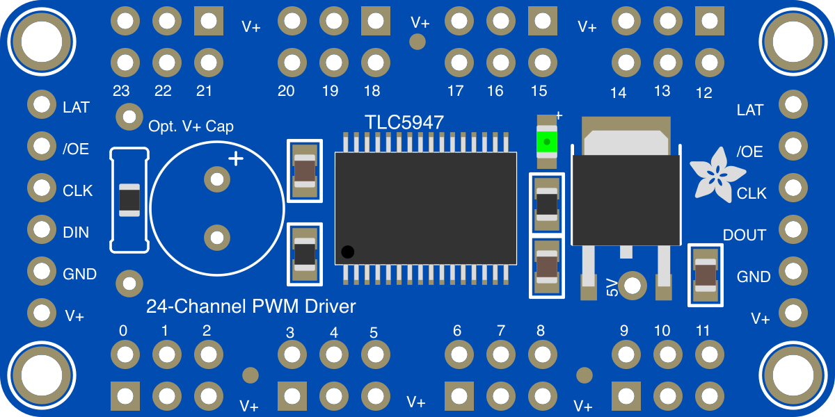
 Design with 24-Channel 12-bit PWM LED Driver - SPI in Cirkit Designer
Introduction
The 24-Channel 12-bit PWM LED Driver (Adafruit Part ID: 1429) is a specialized driver designed to control the brightness and color of LEDs with high precision. It features 24 independent channels, each capable of 12-bit pulse-width modulation (PWM), allowing for smooth and accurate dimming. The driver communicates with microcontrollers via the Serial Peripheral Interface (SPI), ensuring fast and efficient data transfer.
This component is ideal for applications requiring precise LED control, such as:
- RGB LED matrices and displays
- LED-based lighting systems
- Artistic lighting installations
- Industrial indicator systems
- Any project requiring multi-channel LED dimming
Explore Projects Built with 24-Channel 12-bit PWM LED Driver - SPI
 Open Project in Cirkit Designer
 Open Project in Cirkit Designer
 Open Project in Cirkit Designer
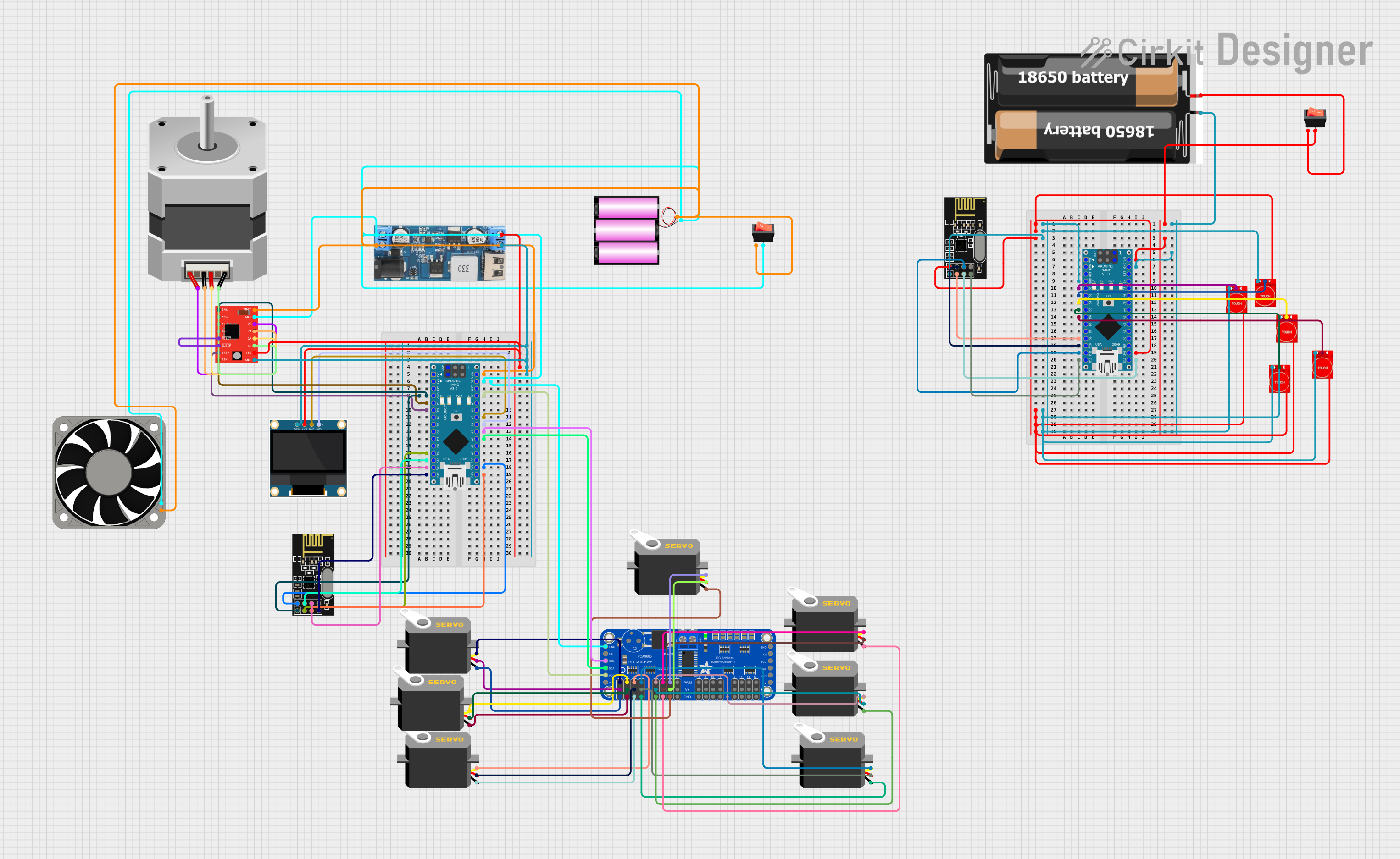 Open Project in Cirkit Designer
Explore Projects Built with 24-Channel 12-bit PWM LED Driver - SPI
Open Project in Cirkit DesignerOpen Project in Cirkit DesignerOpen Project in Cirkit DesignerOpen Project in Cirkit DesignerTechnical Specifications
Below are the key technical details of the 24-Channel 12-bit PWM LED Driver:
| Parameter | Value |
|---|---|
| Manufacturer | Adafruit |
| Part ID | 1429 |
| Channels | 24 |
| PWM Resolution | 12-bit (4096 levels) |
| Communication Protocol | SPI |
| Input Voltage Range | 3.3V to 5V (logic level) |
| Output Voltage Range | Up to 17V (LED supply voltage) |
| Maximum Output Current | 15mA per channel (constant current sink) |
| Operating Temperature | -40°C to +85°C |
| Package Type | Surface Mount |
Pin Configuration and Descriptions
The driver has the following pin configuration:
| Pin Name | Type | Description |
|---|---|---|
| VCC | Power Input | Logic voltage input (3.3V or 5V). |
| GND | Ground | Ground connection. |
| SDI | SPI Input | Serial Data Input. Receives data from the microcontroller. |
| SDO | SPI Output | Serial Data Output. Passes data to the next device in a daisy-chain setup. |
| SCLK | SPI Clock | Serial Clock Input. Synchronizes data transfer with the microcontroller. |
| LAT | Latch Input | Latches the PWM data into the output registers. |
| OE | Output Enable | Active-low pin to enable or disable all outputs. |
| OUT0-OUT23 | Output Channels | 24 constant-current sink outputs for driving LEDs. |
Usage Instructions
How to Use the Component in a Circuit
- Power Supply: Connect the VCC pin to a 3.3V or 5V power source, depending on your microcontroller's logic level. Connect the GND pin to the ground of your circuit.
- SPI Connections:
- Connect the SDI pin to the SPI MOSI pin of your microcontroller.
- Connect the SCLK pin to the SPI clock pin of your microcontroller.
- If using multiple drivers in a daisy-chain configuration, connect the SDO pin of the first driver to the SDI pin of the next driver.
- Latch and Enable:
- Connect the LAT pin to a GPIO pin on your microcontroller to control when data is latched into the output registers.
- Connect the OE pin to another GPIO pin or ground it to enable the outputs.
- LED Connections: Connect the cathodes of your LEDs to the OUT0-OUT23 pins. The anodes should be connected to the LED supply voltage (up to 17V).
Important Considerations and Best Practices
- Use current-limiting resistors or ensure the driver is configured to sink the appropriate current for your LEDs.
- Ensure the SPI clock speed is within the driver's supported range for reliable communication.
- If driving high-power LEDs, ensure proper heat dissipation and consider using external transistors if needed.
- Avoid exceeding the maximum output current of 15mA per channel to prevent damage to the driver.
Example Code for Arduino UNO
Below is an example of how to control the 24-Channel 12-bit PWM LED Driver using an Arduino UNO:
#include <SPI.h>

// Define SPI pins
#define LATCH_PIN 10  // Pin connected to LAT
#define OE_PIN 9      // Pin connected to OE (active-low)

void setup() {
  // Initialize SPI
  SPI.begin();
  SPI.setClockDivider(SPI_CLOCK_DIV16); // Set SPI clock speed
  SPI.setDataMode(SPI_MODE0);           // Set SPI mode
  pinMode(LATCH_PIN, OUTPUT);
  pinMode(OE_PIN, OUTPUT);

  // Enable outputs
  digitalWrite(OE_PIN, LOW);
}

void loop() {
  // Example: Set all channels to 50% brightness
  digitalWrite(LATCH_PIN, LOW); // Begin latching data

  for (int i = 0; i < 24; i++) {
    // Send 12-bit PWM value (2048 = 50% brightness)
    SPI.transfer(0x08); // High byte (12-bit value: 0x0800)
    SPI.transfer(0x00); // Low byte
  }

  digitalWrite(LATCH_PIN, HIGH); // Latch data into output registers
  delay(1000); // Wait for 1 second

  // Example: Turn off all channels
  digitalWrite(LATCH_PIN, LOW); // Begin latching data

  for (int i = 0; i < 24; i++) {
    SPI.transfer(0x00); // High byte (12-bit value: 0x0000)
    SPI.transfer(0x00); // Low byte
  }

  digitalWrite(LATCH_PIN, HIGH); // Latch data into output registers
  delay(1000); // Wait for 1 second
}
Troubleshooting and FAQs
Common Issues and Solutions
No Output from LEDs:
- Ensure the OE pin is pulled low to enable the outputs.
- Verify that the SPI connections (SDI, SCLK, LAT) are correctly wired.
- Check the LED connections and ensure the anodes are connected to the supply voltage.
Flickering LEDs:
- Verify that the SPI clock speed is within the supported range.
- Ensure the latch timing is correct and that data is latched after being sent.
Overheating Driver:
- Ensure the output current per channel does not exceed 15mA.
- Check for proper ventilation or heat dissipation if driving many LEDs.
Incorrect Brightness Levels:
- Verify that the 12-bit PWM values are being sent correctly.
- Ensure the SPI data format matches the driver's requirements.
FAQs
Q: Can I daisy-chain multiple drivers?
A: Yes, you can connect the SDO pin of one driver to the SDI pin of the next driver to control multiple drivers with a single SPI interface.
Q: What is the maximum LED supply voltage?
A: The driver supports an LED supply voltage of up to 17V.
Q: Can I use this driver with 3.3V logic microcontrollers?
A: Yes, the driver is compatible with both 3.3V and 5V logic levels.
Q: How do I calculate the required current-limiting resistor for my LEDs?
A: Use the formula: R = (V_supply - V_f) / I, where V_supply is the LED supply voltage, V_f is the forward voltage of the LED, and I is the desired current.
This documentation provides a comprehensive guide to using the Adafruit 24-Channel 12-bit PWM LED Driver (Part ID: 1429). For further assistance, refer to the manufacturer's datasheet or support resources.