How to Use Arduino Modulino Knob: Examples, Pinouts, and Specs
Introduction
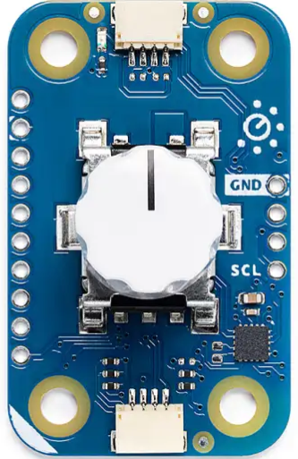
The Arduino Modulino Knob (ABX00107) is a rotary input device designed for seamless integration with Arduino projects. This component allows users to adjust values or settings by simply turning the knob, making it ideal for applications requiring user input, such as volume control, menu navigation, or parameter adjustments. Its compact design and ease of use make it a versatile addition to any project.
Explore Projects Built with Arduino Modulino Knob

Explore Projects Built with Arduino Modulino Knob
Common Applications and Use Cases
- Volume or brightness control in audio and lighting systems
- Menu navigation in embedded systems
- Adjustable parameter tuning in robotics and automation
- User input for DIY Arduino projects
Technical Specifications
The Arduino Modulino Knob is designed to provide reliable and precise rotary input. Below are its key technical details:
General Specifications
| Parameter | Value |
|---|---|
| Manufacturer | Arduino |
| Part ID | ABX00107 |
| Operating Voltage | 3.3V - 5V |
| Maximum Current | 10 mA |
| Output Type | Digital (rotary encoder) |
| Rotational Steps | 20 steps per revolution |
| Push Button Function | Integrated (momentary switch) |
| Operating Temperature | -10°C to 70°C |
| Dimensions | 20mm x 20mm x 15mm |
Pin Configuration and Descriptions
The Modulino Knob has a 5-pin interface for easy connection to an Arduino or other microcontroller. Below is the pinout:
| Pin Number | Pin Name | Description |
|---|---|---|
| 1 | GND | Ground connection |
| 2 | VCC | Power supply (3.3V or 5V) |
| 3 | CLK | Clock signal output from the rotary encoder |
| 4 | DT | Data signal output from the rotary encoder |
| 5 | SW | Push button signal output (active LOW) |
Usage Instructions
The Arduino Modulino Knob is straightforward to use in a circuit. Follow the steps below to integrate it into your project:
Connecting the Modulino Knob
- Power the Knob: Connect the
VCCpin to the 3.3V or 5V pin on your Arduino and theGNDpin to the Arduino's ground. - Connect the Rotary Encoder:
- Connect the
CLKpin to a digital input pin on the Arduino (e.g., D2). - Connect the
DTpin to another digital input pin (e.g., D3).
- Connect the
- Connect the Push Button:
- Connect the
SWpin to a digital input pin (e.g., D4). Use a pull-up resistor if necessary.
- Connect the
Sample Arduino Code
Below is an example sketch to read the rotary encoder and push button inputs:
// Define pin connections
#define CLK 2  // Clock pin
#define DT 3   // Data pin
#define SW 4   // Switch pin

int lastStateCLK;  // To store the previous state of the CLK pin
int currentStateCLK;  // To store the current state of the CLK pin
int counter = 0;  // Counter to track rotary position

void setup() {
  pinMode(CLK, INPUT);
  pinMode(DT, INPUT);
  pinMode(SW, INPUT_PULLUP);  // Use internal pull-up for the switch

  Serial.begin(9600);  // Initialize serial communication
  lastStateCLK = digitalRead(CLK);  // Read the initial state of the CLK pin
}

void loop() {
  // Read the current state of the CLK pin
  currentStateCLK = digitalRead(CLK);

  // Check if the state has changed
  if (currentStateCLK != lastStateCLK) {
    // Determine the direction of rotation
    if (digitalRead(DT) != currentStateCLK) {
      counter++;  // Clockwise rotation
    } else {
      counter--;  // Counterclockwise rotation
    }

    // Print the counter value to the Serial Monitor
    Serial.print("Counter: ");
    Serial.println(counter);
  }

  // Update the last state of the CLK pin
  lastStateCLK = currentStateCLK;

  // Check if the push button is pressed
  if (digitalRead(SW) == LOW) {
    Serial.println("Button Pressed!");
    delay(200);  // Debounce delay
  }
}
Important Considerations and Best Practices
- Debouncing: The rotary encoder and push button may produce noise or false signals. Use software debouncing or external capacitors to filter out unwanted signals.
- Pull-up Resistors: Ensure the
SWpin is connected to a pull-up resistor (internal or external) to avoid floating states. - Power Supply: Operate the Modulino Knob within its specified voltage range (3.3V - 5V) to prevent damage.
Troubleshooting and FAQs
Common Issues and Solutions
The knob is not responding to rotation.
- Check the connections to the
CLKandDTpins. Ensure they are securely connected to the correct Arduino pins. - Verify that the
VCCandGNDpins are properly connected to the power supply.
- Check the connections to the
The push button does not register presses.
- Ensure the
SWpin is connected to a digital input pin with a pull-up resistor. - Check for loose connections or damaged wires.
- Ensure the
The counter value is erratic or jumps unexpectedly.
- Add software debouncing to filter out noise from the rotary encoder signals.
- Use shielded cables if the Modulino Knob is used in a noisy environment.
The knob does not work with a 3.3V power supply.
- Ensure the Arduino board and the Modulino Knob share a common ground.
- Verify that the Arduino's digital input pins can reliably detect 3.3V signals.
FAQs
Q: Can I use the Modulino Knob with a 3.3V-only microcontroller?
A: Yes, the Modulino Knob is compatible with 3.3V systems. Ensure all connections are properly configured.
Q: How do I increase the resolution of the rotary encoder?
A: The Modulino Knob has a fixed resolution of 20 steps per revolution. For higher resolution, consider using a different encoder model.
Q: Can I use multiple Modulino Knobs in the same project?
A: Yes, you can use multiple knobs by connecting each to separate digital input pins on your Arduino.
Q: Is the push button on the knob momentary or latching?
A: The push button is momentary, meaning it only stays active while pressed.
By following this documentation, you can effectively integrate the Arduino Modulino Knob into your projects and troubleshoot any issues that arise.