How to Use DFRobot Solar Power Manager 5V: Examples, Pinouts, and Specs
Introduction
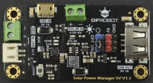
The DFRobot Solar Power Manager 5V is a compact and efficient solar power management module designed to regulate and manage solar energy. It provides a stable 5V output, making it ideal for powering low-power devices and charging lithium-ion or lithium-polymer batteries. This module is specifically engineered to maximize the efficiency of solar energy harvesting while ensuring safe and reliable operation.
Explore Projects Built with DFRobot Solar Power Manager 5V
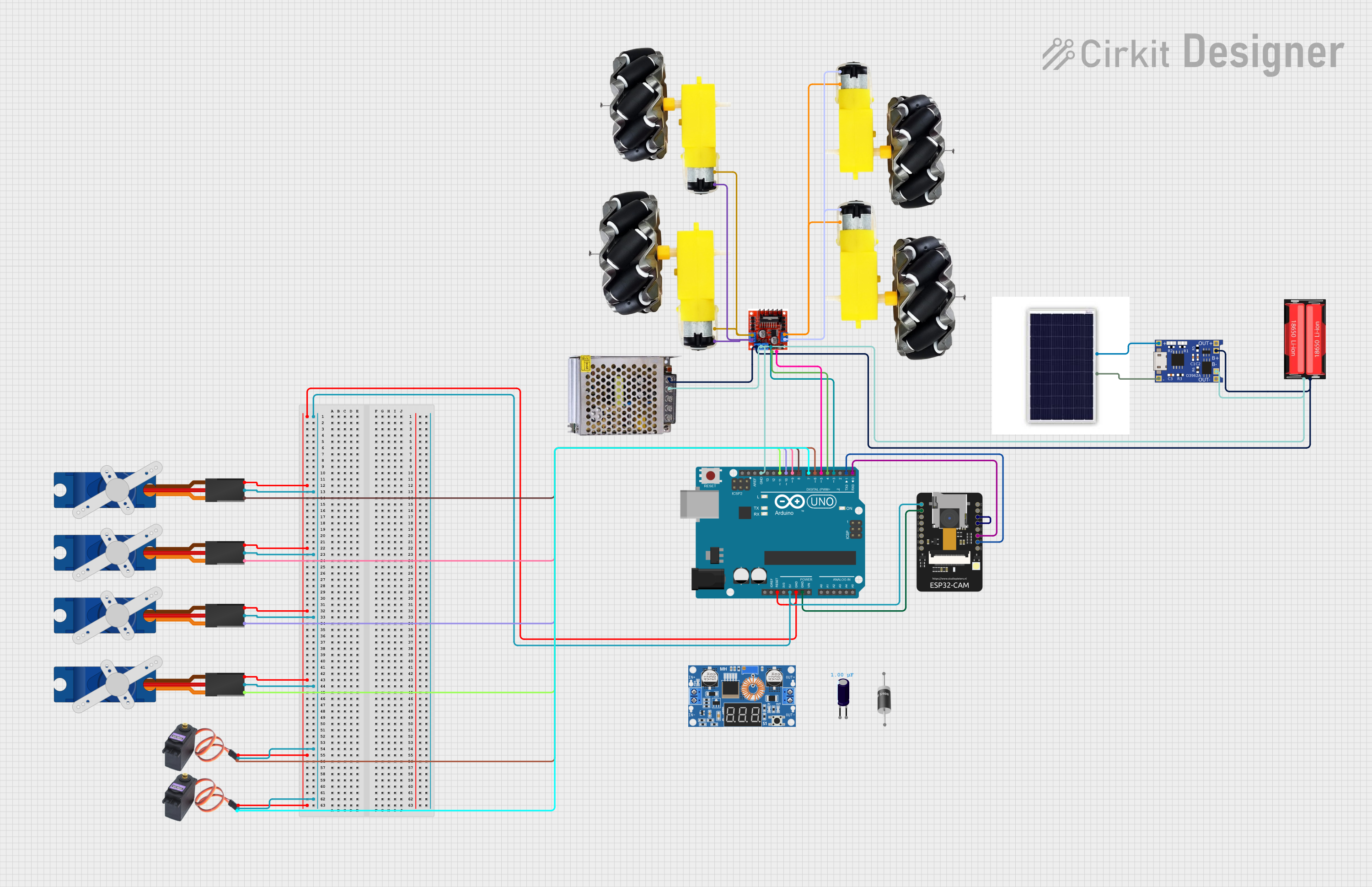
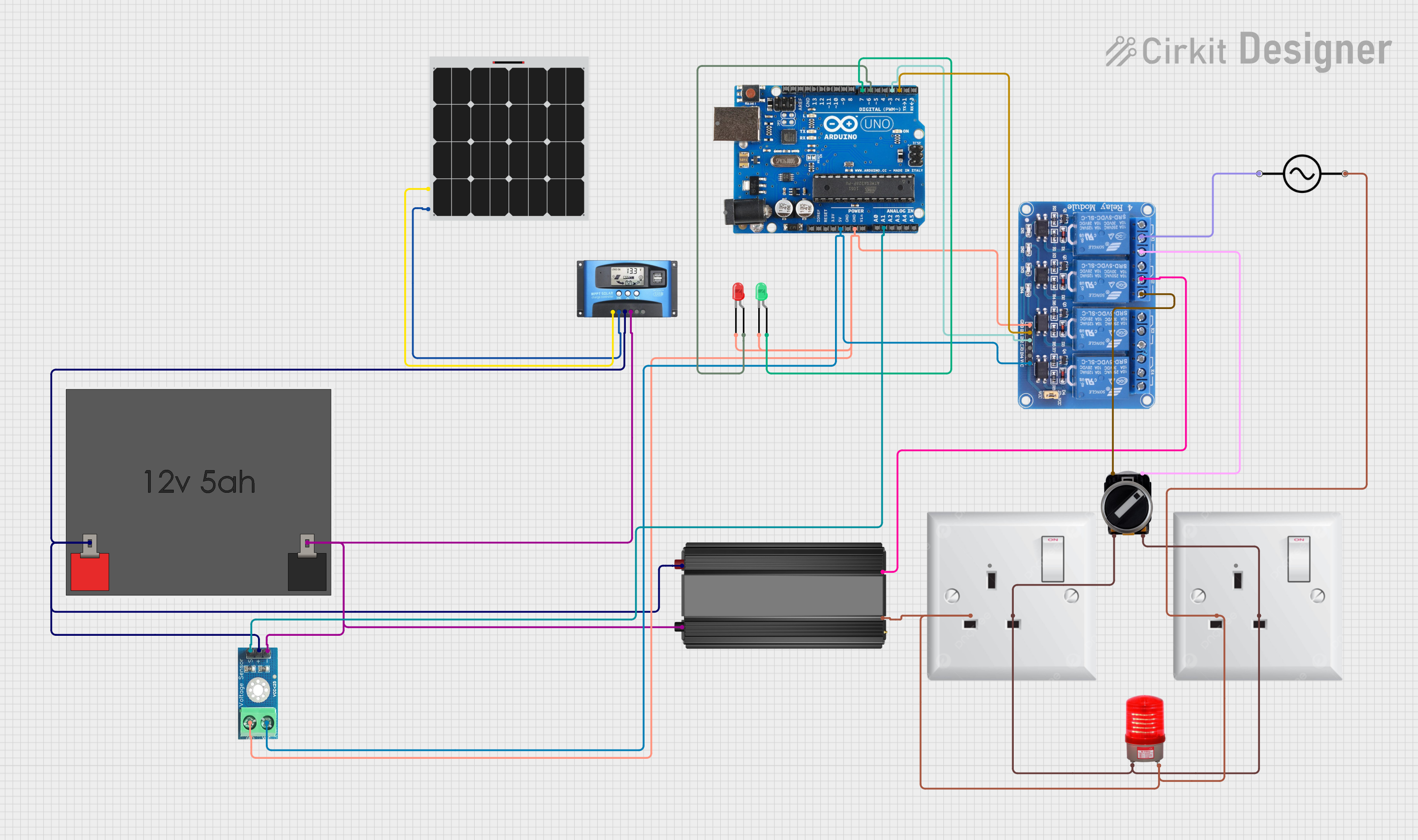
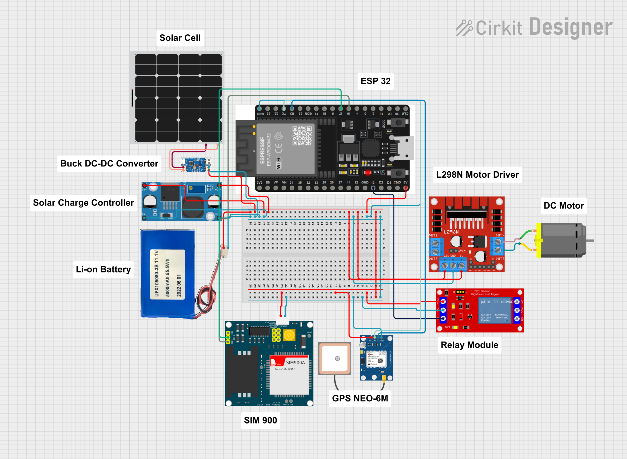
Explore Projects Built with DFRobot Solar Power Manager 5V
Common Applications and Use Cases
- Solar-powered IoT devices
- Outdoor environmental monitoring systems
- Remote sensing and data logging
- Portable solar charging stations
- DIY solar energy projects
Technical Specifications
The following table outlines the key technical details of the DFRobot Solar Power Manager 5V:
| Parameter | Value |
|---|---|
| Input Voltage Range | 4.4V to 6V (Solar Panel Input) |
| Output Voltage | 5V (Regulated) |
| Output Current | Up to 1A |
| Battery Charging Voltage | 4.2V (for Li-ion/LiPo batteries) |
| Battery Charging Current | 500mA (default, adjustable via resistor) |
| Efficiency | Up to 96% |
| Operating Temperature | -40°C to 85°C |
| Dimensions | 50mm x 37mm |
Pin Configuration and Descriptions
The DFRobot Solar Power Manager 5V features several input/output pins and connectors. The table below describes each pin:
| Pin/Connector | Description |
|---|---|
| VIN | Solar panel input (4.4V to 6V). Connect the positive terminal of the solar panel here. |
| GND | Ground connection for the solar panel and other components. |
| BAT+ | Positive terminal for the rechargeable battery. |
| BAT- | Negative terminal for the rechargeable battery. |
| USB IN | Micro-USB input for charging the battery or powering the module. |
| 5V OUT | Regulated 5V output for powering external devices. |
| STAT1/STAT2 | Status indicator pins for battery charging (can be connected to LEDs). |
Usage Instructions
How to Use the Component in a Circuit
- Connect the Solar Panel: Attach the positive and negative terminals of a solar panel (4.4V to 6V) to the
VINandGNDpins, respectively. - Connect the Battery: Connect a single-cell lithium-ion or lithium-polymer battery to the
BAT+andBAT-terminals. Ensure correct polarity to avoid damage. - Power External Devices: Use the
5V OUTpin to power external devices. The output is regulated to 5V and can supply up to 1A of current. - Monitor Charging Status: Optionally, connect LEDs to the
STAT1andSTAT2pins to monitor the battery charging status.
Important Considerations and Best Practices
- Battery Compatibility: Only use single-cell Li-ion or LiPo batteries with a nominal voltage of 3.7V and a maximum charging voltage of 4.2V.
- Solar Panel Selection: Use a solar panel with an output voltage between 4.4V and 6V for optimal performance.
- Heat Dissipation: Ensure adequate ventilation around the module to prevent overheating during operation.
- Adjusting Charging Current: The default charging current is 500mA. To adjust it, replace the current-setting resistor (refer to the DFRobot datasheet for details).
- Reverse Polarity Protection: Double-check all connections to avoid reverse polarity, which can damage the module.
Example: Using with an Arduino UNO
The DFRobot Solar Power Manager 5V can be used to power an Arduino UNO. Below is an example circuit and code:
Circuit Setup
- Connect the
5V OUTpin of the Solar Power Manager to the5Vpin of the Arduino UNO. - Connect the
GNDpin of the Solar Power Manager to theGNDpin of the Arduino UNO.
Example Code
// Example code for reading a sensor powered by the Solar Power Manager 5V
// This code reads data from an analog sensor and prints it to the Serial Monitor.

const int sensorPin = A0; // Analog pin connected to the sensor
int sensorValue = 0;      // Variable to store the sensor reading

void setup() {
  Serial.begin(9600); // Initialize serial communication at 9600 baud
  pinMode(sensorPin, INPUT); // Set the sensor pin as an input
}

void loop() {
  sensorValue = analogRead(sensorPin); // Read the sensor value
  Serial.print("Sensor Value: ");      // Print a label for the sensor value
  Serial.println(sensorValue);         // Print the sensor value
  delay(1000);                         // Wait for 1 second before the next reading
}
Troubleshooting and FAQs
Common Issues and Solutions
No Output Voltage on 5V OUT Pin
- Cause: Insufficient input voltage from the solar panel or battery.
- Solution: Ensure the solar panel provides at least 4.4V. Check the battery connection and charge level.
Battery Not Charging
- Cause: Incorrect battery connection or incompatible battery type.
- Solution: Verify the battery polarity and ensure it is a single-cell Li-ion or LiPo battery.
Overheating
- Cause: Excessive current draw or poor ventilation.
- Solution: Reduce the load on the
5V OUTpin and ensure proper airflow around the module.
LED Indicators Not Working
- Cause: LEDs not connected properly or incorrect resistor values.
- Solution: Check the LED connections and use appropriate current-limiting resistors.
FAQs
Q: Can I use a solar panel with an output voltage higher than 6V?
A: No, the module is designed for solar panels with an output voltage between 4.4V and 6V. Using a higher voltage may damage the module.
Q: Can I power the module using only a USB connection?
A: Yes, the module can be powered via the USB IN port, which can also charge the connected battery.
Q: What is the maximum load current supported by the 5V OUT pin?
A: The 5V OUT pin can supply up to 1A of current.
Q: How do I adjust the battery charging current?
A: The charging current can be adjusted by replacing the current-setting resistor. Refer to the DFRobot datasheet for detailed instructions.