Cirkit Designer Logo
Cirkit Designer
Your all-in-one circuit design IDE
Home / 
Component Documentation

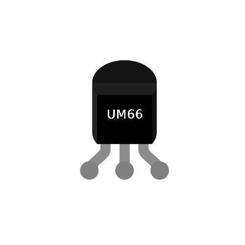
How to Use UM66: Examples, Pinouts, and Specs

Image of UM66
Cirkit Designer LogoDesign with UM66 in Cirkit Designer

Introduction

The UM66 is a melody generator integrated circuit (IC) designed to produce pre-programmed musical tones. It is a low-power, easy-to-use component that outputs a melody when powered. The IC is widely used in applications such as musical greeting cards, toys, doorbells, and other sound-generating devices. Its compact size and simplicity make it an ideal choice for projects requiring basic sound generation.

Explore Projects Built with UM66

Use Cirkit Designer to design, explore, and prototype these projects online. Some projects support real-time simulation. Click "Open Project" to start designing instantly!
Battery-Powered Emergency Alert System with NUCLEO-F072RB, SIM800L, and GPS NEO 6M
Image of women safety: A project utilizing UM66 in a practical application
This circuit is an emergency alert system that uses a NUCLEO-F072RB microcontroller to send SMS alerts and make calls via a SIM800L GSM module, while obtaining location data from a GPS NEO 6M module. The system is powered by a Li-ion battery and includes a TP4056 module for battery charging and protection, with a rocker switch to control power to the microcontroller.
Cirkit Designer LogoOpen Project in Cirkit Designer
Battery-Powered Line Following Robot with IR Sensors and Cytron URC10 Motor Controller
Image of URC10 SUMO AUTO: A project utilizing UM66 in a practical application
This circuit is a robotic control system that uses multiple IR sensors for line detection and obstacle avoidance, powered by a 3S LiPo battery. The Cytron URC10 motor driver, controlled by a microcontroller, drives two GM25 DC motors based on input from the sensors and a rocker switch, with a 7-segment panel voltmeter displaying the battery voltage.
Cirkit Designer LogoOpen Project in Cirkit Designer
Battery-Powered Remote-Controlled Dual Motor System with Cytron URC10
Image of URC10 SUMO RC: A project utilizing UM66 in a practical application
This circuit is a remote-controlled dual DC motor driver system powered by a 3S LiPo battery. It uses a Cytron URC10 motor driver to control two GM25 DC motors based on signals received from an R6FG receiver, with a rocker switch for power control and a 7-segment panel voltmeter for monitoring the battery voltage.
Cirkit Designer LogoOpen Project in Cirkit Designer
Arduino-Controlled Obstacle Avoiding Robot with Ultrasonic Sensor and L298N Motor Driver
Image of مشروع مركبة ذاتية تتفادى الحواجز: A project utilizing UM66 in a practical application
This is a mobile robot platform controlled by an Arduino UNO with a sensor shield. It uses an HC-SR04 ultrasonic sensor for obstacle detection and a servo motor for directional control. The robot's movement is powered by gearmotors controlled by an L298N motor driver, and it is designed to navigate by avoiding obstacles detected by the ultrasonic sensor.
Cirkit Designer LogoOpen Project in Cirkit Designer

Explore Projects Built with UM66

Use Cirkit Designer to design, explore, and prototype these projects online. Some projects support real-time simulation. Click "Open Project" to start designing instantly!
Image of women safety: A project utilizing UM66 in a practical application
Battery-Powered Emergency Alert System with NUCLEO-F072RB, SIM800L, and GPS NEO 6M
This circuit is an emergency alert system that uses a NUCLEO-F072RB microcontroller to send SMS alerts and make calls via a SIM800L GSM module, while obtaining location data from a GPS NEO 6M module. The system is powered by a Li-ion battery and includes a TP4056 module for battery charging and protection, with a rocker switch to control power to the microcontroller.
Cirkit Designer LogoOpen Project in Cirkit Designer
Image of URC10 SUMO AUTO: A project utilizing UM66 in a practical application
Battery-Powered Line Following Robot with IR Sensors and Cytron URC10 Motor Controller
This circuit is a robotic control system that uses multiple IR sensors for line detection and obstacle avoidance, powered by a 3S LiPo battery. The Cytron URC10 motor driver, controlled by a microcontroller, drives two GM25 DC motors based on input from the sensors and a rocker switch, with a 7-segment panel voltmeter displaying the battery voltage.
Cirkit Designer LogoOpen Project in Cirkit Designer
Image of URC10 SUMO RC: A project utilizing UM66 in a practical application
Battery-Powered Remote-Controlled Dual Motor System with Cytron URC10
This circuit is a remote-controlled dual DC motor driver system powered by a 3S LiPo battery. It uses a Cytron URC10 motor driver to control two GM25 DC motors based on signals received from an R6FG receiver, with a rocker switch for power control and a 7-segment panel voltmeter for monitoring the battery voltage.
Cirkit Designer LogoOpen Project in Cirkit Designer
Image of مشروع مركبة ذاتية تتفادى الحواجز: A project utilizing UM66 in a practical application
Arduino-Controlled Obstacle Avoiding Robot with Ultrasonic Sensor and L298N Motor Driver
This is a mobile robot platform controlled by an Arduino UNO with a sensor shield. It uses an HC-SR04 ultrasonic sensor for obstacle detection and a servo motor for directional control. The robot's movement is powered by gearmotors controlled by an L298N motor driver, and it is designed to navigate by avoiding obstacles detected by the ultrasonic sensor.
Cirkit Designer LogoOpen Project in Cirkit Designer

Technical Specifications

The UM66 is available in different variants, each programmed with a specific melody. Below are the key technical details of the UM66 IC:

  • Operating Voltage: 1.5V to 4.5V DC
  • Typical Operating Voltage: 3V DC
  • Output Frequency: Pre-programmed melody
  • Output Type: Digital signal (requires an external transistor to drive a speaker)
  • Current Consumption: < 1mA
  • Package Type: TO-92 (commonly)

Pin Configuration and Descriptions

The UM66 IC has three pins, as described in the table below:

Pin Number Pin Name Description
1 VCC Power supply pin (1.5V to 4.5V DC)
2 GND Ground pin
3 OUT Melody output pin (connect to a transistor base)

Usage Instructions

How to Use the UM66 in a Circuit

  1. Power Supply: Connect the VCC pin to a DC voltage source (1.5V to 4.5V) and the GND pin to the ground of the circuit.
  2. Output Connection: The OUT pin provides a digital signal that needs to be amplified to drive a speaker. Connect the OUT pin to the base of an NPN transistor (e.g., BC547) through a current-limiting resistor (e.g., 1kΩ). The transistor will act as a switch to drive the speaker.
  3. Speaker Connection: Connect the speaker between the collector of the transistor and the positive supply voltage. Add a flyback diode (e.g., 1N4148) across the speaker to protect the circuit from voltage spikes.

Example Circuit Diagram

Below is a simple circuit to use the UM66 IC with a speaker:

   +3V DC
     |
     R (1kΩ)
     |
     |-----> UM66 (OUT pin)
     |         |
     |         |
     |         GND
     |
     Q (BC547)
     |
     |-----> Speaker
     |
    GND

Important Considerations

  • Ensure the supply voltage does not exceed 4.5V, as this may damage the IC.
  • Use a current-limiting resistor between the OUT pin and the transistor base to prevent excessive current flow.
  • The UM66 cannot directly drive a speaker; always use a transistor for amplification.
  • For better sound quality, use a small capacitor (e.g., 0.1µF) across the power supply pins to filter noise.

Arduino UNO Example Code

The UM66 can be triggered using an Arduino UNO to control when the melody plays. Below is an example code snippet:

// Example code to control UM66 melody IC with Arduino UNO
// Connect the OUT pin of UM66 to a transistor base (via a resistor)
// The transistor drives the speaker connected to the circuit

const int melodyPin = 7; // Pin connected to the VCC of UM66

void setup() {
  pinMode(melodyPin, OUTPUT); // Set the pin as output
}

void loop() {
  digitalWrite(melodyPin, HIGH); // Turn on the UM66 to play melody
  delay(5000);                  // Play melody for 5 seconds
  digitalWrite(melodyPin, LOW); // Turn off the UM66
  delay(2000);                  // Wait for 2 seconds before replaying
}

Troubleshooting and FAQs

Common Issues and Solutions

  1. No Sound from the Speaker:

    • Cause: Incorrect wiring or insufficient power supply.
    • Solution: Double-check the circuit connections and ensure the supply voltage is within the specified range (1.5V to 4.5V).
  2. Distorted Sound:

    • Cause: Noise in the power supply or incorrect speaker impedance.
    • Solution: Add a decoupling capacitor (e.g., 0.1µF) across the power supply pins and use a speaker with an impedance of 8Ω.
  3. UM66 Overheating:

    • Cause: Supply voltage exceeds 4.5V.
    • Solution: Use a regulated power supply to ensure the voltage stays within the safe operating range.
  4. Melody Stops Abruptly:

    • Cause: Insufficient current supply or loose connections.
    • Solution: Ensure the power source can provide enough current and check all connections.

FAQs

Q1: Can I change the melody of the UM66?
A1: No, the melody is pre-programmed into the IC and cannot be changed. You can select a different UM66 variant for a different melody.

Q2: Can the UM66 directly drive a speaker?
A2: No, the UM66 output is not strong enough to drive a speaker directly. Use a transistor as an amplifier.

Q3: What type of transistor should I use with the UM66?
A3: An NPN transistor like BC547 or 2N2222 is commonly used to amplify the output signal.

Q4: Can I use the UM66 with a 5V power supply?
A4: No, the maximum operating voltage of the UM66 is 4.5V. Use a voltage regulator (e.g., 3.3V regulator) if your power source is 5V.

By following this documentation, you can effectively use the UM66 melody generator IC in your projects.