Cirkit Designer Logo
Cirkit Designer
Your all-in-one circuit design IDE
Home / 
Component Documentation

How to Use Speray + Button: Examples, Pinouts, and Specs

Image of Speray + Button
Cirkit Designer LogoDesign with Speray + Button in Cirkit Designer

Introduction

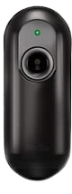
The Speray + Button is a versatile input device manufactured by Arduino, part ID MEGA. It combines a button and an infrared (IR) proximity sensor in a single module, allowing users to detect both physical button presses and nearby objects. This dual-functionality makes it ideal for interactive projects, robotics, and automation systems.

Common applications include:

  • Detecting user input through button presses
  • Proximity-based object detection
  • Triggering events in robotics or IoT systems
  • Interactive installations and games

Explore Projects Built with Speray + Button

Use Cirkit Designer to design, explore, and prototype these projects online. Some projects support real-time simulation. Click "Open Project" to start designing instantly!
ESP32-Controlled OLED Display with Button Interface
Image of RRR: A project utilizing Speray + Button in a practical application
This circuit features an ESP32 microcontroller connected to a 0.96" OLED display and a green button. The ESP32 powers the OLED display and communicates with it via I2C (with SDA and SCK connected to pins D21 and D22, respectively). The green button is connected to the ESP32's digital input pin D4, allowing it to trigger actions when pressed.
Cirkit Designer LogoOpen Project in Cirkit Designer
8-Channel Multiplexer with Pushbutton Inputs and Resistor Network
Image of 8 push pull buttons one mux: A project utilizing Speray + Button in a practical application
This circuit uses a SparkFun 74HC4051 8-Channel Multiplexer to read the states of eight pushbuttons. Each pushbutton is connected to a corresponding input channel on the multiplexer through a 2k Ohm resistor, allowing the multiplexer to sequentially read the button states and output them to a single data line.
Cirkit Designer LogoOpen Project in Cirkit Designer
Battery-Powered Multi-Button Controller with Seeed Studio nRF52840
Image of RetroBle Atari Controller: A project utilizing Speray + Button in a practical application
This circuit consists of five pushbuttons connected to a Seeed Studio nRF52840 microcontroller, which is powered by a Polymer Lithium Ion Battery. Each pushbutton is connected to a different GPIO pin on the microcontroller, allowing for individual button press detection and processing.
Cirkit Designer LogoOpen Project in Cirkit Designer
Pushbutton-Controlled LED Circuit with Capacitor Smoothing
Image of cirkit designer project3: A project utilizing Speray + Button in a practical application
This is a simple pushbutton-controlled LED circuit with a voltage stabilization or power reserve feature provided by an electrolytic capacitor. Pressing either pushbutton will complete the circuit, allowing current to flow from the 4 x AAA batteries through the LED, causing it to illuminate.
Cirkit Designer LogoOpen Project in Cirkit Designer

Explore Projects Built with Speray + Button

Use Cirkit Designer to design, explore, and prototype these projects online. Some projects support real-time simulation. Click "Open Project" to start designing instantly!
Image of RRR: A project utilizing Speray + Button in a practical application
ESP32-Controlled OLED Display with Button Interface
This circuit features an ESP32 microcontroller connected to a 0.96" OLED display and a green button. The ESP32 powers the OLED display and communicates with it via I2C (with SDA and SCK connected to pins D21 and D22, respectively). The green button is connected to the ESP32's digital input pin D4, allowing it to trigger actions when pressed.
Cirkit Designer LogoOpen Project in Cirkit Designer
Image of 8 push pull buttons one mux: A project utilizing Speray + Button in a practical application
8-Channel Multiplexer with Pushbutton Inputs and Resistor Network
This circuit uses a SparkFun 74HC4051 8-Channel Multiplexer to read the states of eight pushbuttons. Each pushbutton is connected to a corresponding input channel on the multiplexer through a 2k Ohm resistor, allowing the multiplexer to sequentially read the button states and output them to a single data line.
Cirkit Designer LogoOpen Project in Cirkit Designer
Image of RetroBle Atari Controller: A project utilizing Speray + Button in a practical application
Battery-Powered Multi-Button Controller with Seeed Studio nRF52840
This circuit consists of five pushbuttons connected to a Seeed Studio nRF52840 microcontroller, which is powered by a Polymer Lithium Ion Battery. Each pushbutton is connected to a different GPIO pin on the microcontroller, allowing for individual button press detection and processing.
Cirkit Designer LogoOpen Project in Cirkit Designer
Image of cirkit designer project3: A project utilizing Speray + Button in a practical application
Pushbutton-Controlled LED Circuit with Capacitor Smoothing
This is a simple pushbutton-controlled LED circuit with a voltage stabilization or power reserve feature provided by an electrolytic capacitor. Pressing either pushbutton will complete the circuit, allowing current to flow from the 4 x AAA batteries through the LED, causing it to illuminate.
Cirkit Designer LogoOpen Project in Cirkit Designer

Technical Specifications

The Speray + Button module is designed for ease of use and compatibility with Arduino boards, including the Arduino MEGA. Below are the key technical details:

General Specifications

Parameter Value
Operating Voltage 3.3V - 5V
Current Consumption < 20mA
Detection Range (IR) 2 cm to 10 cm
Button Type Momentary push button
Output Type Digital (HIGH/LOW)
Dimensions 30mm x 20mm x 10mm

Pin Configuration

The module has 4 pins, as described in the table below:

Pin Name Description
VCC Power supply input (3.3V - 5V)
GND Ground connection
OUT1 Digital output for the button state
OUT2 Digital output for the IR proximity sensor

Usage Instructions

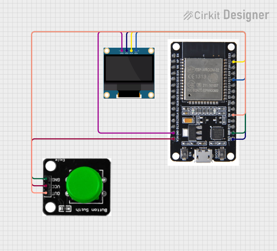
Connecting the Speray + Button to an Arduino MEGA

To use the Speray + Button module, connect it to your Arduino MEGA as follows:

  1. Connect the VCC pin of the module to the 5V pin on the Arduino MEGA.
  2. Connect the GND pin of the module to the GND pin on the Arduino MEGA.
  3. Connect the OUT1 pin to a digital input pin (e.g., D2) on the Arduino MEGA for button state detection.
  4. Connect the OUT2 pin to another digital input pin (e.g., D3) on the Arduino MEGA for proximity detection.

Sample Arduino Code

Below is an example Arduino sketch to read the button state and proximity sensor output:

// Define pin connections
const int buttonPin = 2;  // Pin connected to OUT1 (button output)
const int irPin = 3;      // Pin connected to OUT2 (IR proximity output)

void setup() {
  // Initialize serial communication for debugging
  Serial.begin(9600);

  // Set pin modes
  pinMode(buttonPin, INPUT);
  pinMode(irPin, INPUT);
}

void loop() {
  // Read the button state (HIGH = pressed, LOW = not pressed)
  int buttonState = digitalRead(buttonPin);

  // Read the IR proximity sensor state (HIGH = object detected, LOW = no object)
  int irState = digitalRead(irPin);

  // Print the states to the Serial Monitor
  Serial.print("Button State: ");
  Serial.println(buttonState == HIGH ? "Pressed" : "Not Pressed");

  Serial.print("Proximity Sensor: ");
  Serial.println(irState == HIGH ? "Object Detected" : "No Object");

  // Add a small delay to avoid flooding the Serial Monitor
  delay(200);
}

Important Considerations

  • Ensure the module is powered within the specified voltage range (3.3V - 5V).
  • Avoid placing reflective surfaces too close to the IR sensor, as this may cause false detections.
  • Use pull-down resistors if you experience unstable readings from the button output.

Troubleshooting and FAQs

Common Issues

  1. The button or IR sensor is not responding.

    • Verify all connections are secure and match the pin configuration table.
    • Ensure the module is powered with the correct voltage (3.3V - 5V).
  2. False triggers from the IR sensor.

    • Check for reflective surfaces or strong ambient light near the sensor.
    • Adjust the placement of the module to reduce interference.
  3. Unstable readings from the button.

    • Add a pull-down resistor (10kΩ) to the button output pin to stabilize the signal.

FAQs

Q: Can I use this module with boards other than the Arduino MEGA?
A: Yes, the Speray + Button module is compatible with most Arduino boards, including the UNO, Nano, and Leonardo, as long as the voltage requirements are met.

Q: What is the maximum detection range of the IR sensor?
A: The IR sensor can detect objects within a range of 2 cm to 10 cm.

Q: Can I use both the button and IR sensor simultaneously?
A: Yes, the module provides separate outputs for the button and IR sensor, allowing simultaneous use.

By following this documentation, you can effectively integrate the Speray + Button module into your projects for reliable input and proximity detection.