How to Use 12-bit AS5600 magnetic encoder: Examples, Pinouts, and Specs
Introduction
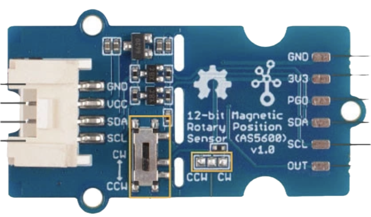
The AS5600 Magnetic Encoder (Manufacturer Part ID: 101020692) by Seeedstudio is a high-resolution rotary encoder designed to provide precise angular position feedback. With a 12-bit resolution, it can measure angles with exceptional accuracy, making it ideal for applications requiring precise motion control. This encoder uses magnetic field sensing technology, eliminating the need for physical contact, which enhances durability and reliability.
Explore Projects Built with 12-bit AS5600 magnetic encoder

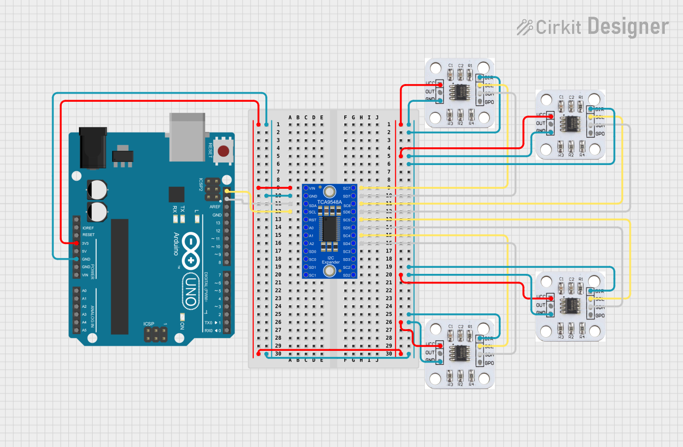
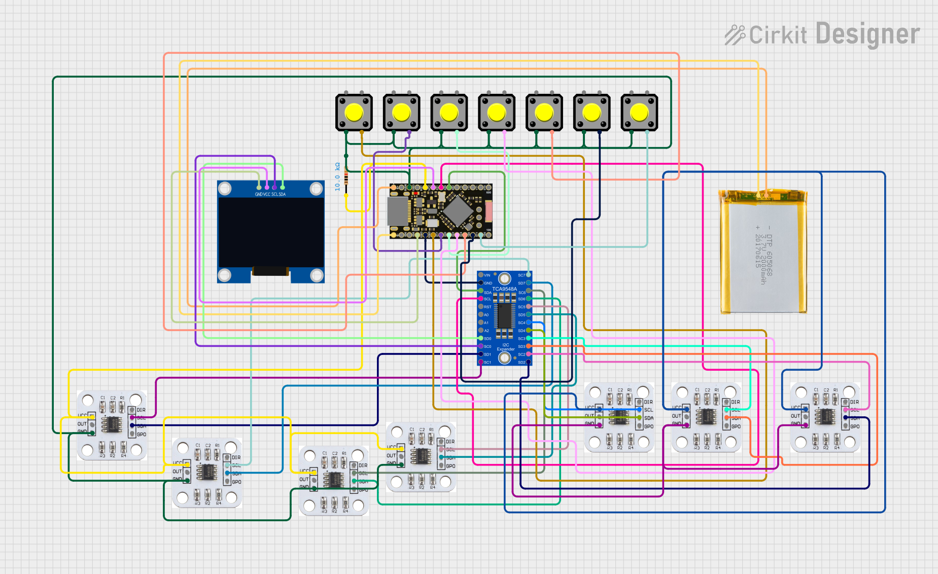
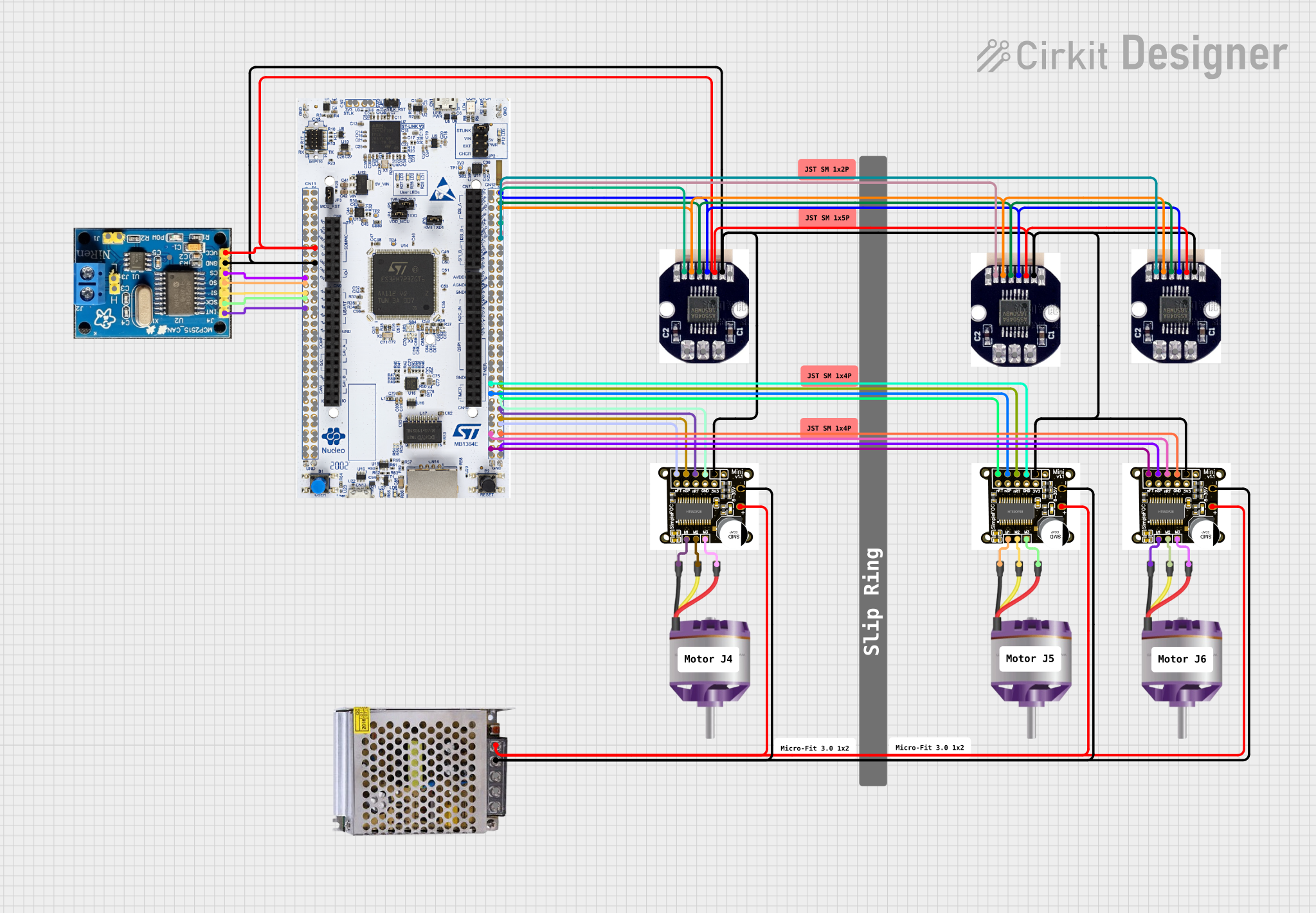
Explore Projects Built with 12-bit AS5600 magnetic encoder
Common Applications
- Robotics: For precise motor control and joint positioning.
- Automation: Used in industrial machinery for accurate angular feedback.
- Consumer Electronics: Integrated into devices requiring rotational input.
- Automotive: Steering angle detection and throttle position sensing.
- Drones: For gimbal stabilization and motor feedback.
Technical Specifications
The AS5600 Magnetic Encoder is a versatile component with the following key specifications:
| Parameter | Value |
|---|---|
| Resolution | 12-bit (4096 positions per revolution) |
| Supply Voltage | 3.3V to 5.5V |
| Current Consumption | 6.5 mA (typical) |
| Interface | I²C and PWM |
| Operating Temperature | -40°C to +125°C |
| Maximum Rotational Speed | 30,000 RPM |
| Magnetic Field Strength | 20 mT to 80 mT |
| Package | SOIC-8 |
Pin Configuration and Descriptions
The AS5600 has 8 pins, as described in the table below:
| Pin Number | Pin Name | Description |
|---|---|---|
| 1 | VDD | Power supply input (3.3V to 5.5V) |
| 2 | GND | Ground |
| 3 | OUT | PWM output for angle measurement |
| 4 | DIR | Direction selection input (high/low) |
| 5 | SDA | I²C data line |
| 6 | SCL | I²C clock line |
| 7 | PROG | Programming pin (used for configuration) |
| 8 | NC | Not connected |
Usage Instructions
How to Use the AS5600 in a Circuit
- Power Supply: Connect the VDD pin to a 3.3V or 5V power source and the GND pin to ground.
- Magnet Placement: Place a diametrically magnetized magnet above the encoder chip. Ensure the magnet is aligned with the center of the chip and within the recommended distance (1-3 mm).
- Interface Selection:
- For I²C communication, connect the SDA and SCL pins to the corresponding pins on your microcontroller.
- For PWM output, connect the OUT pin to an input pin on your microcontroller.
- Direction Control: Use the DIR pin to set the rotation direction. Pull it high or low as needed.
- Programming: Use the PROG pin for advanced configuration if required.
Important Considerations and Best Practices
- Magnet Selection: Use a high-quality diametrically magnetized magnet with a magnetic field strength of 20 mT to 80 mT.
- Alignment: Ensure the magnet is properly centered and at the correct distance from the chip for accurate readings.
- Decoupling Capacitor: Place a 100 nF capacitor close to the VDD and GND pins to reduce noise.
- I²C Pull-Up Resistors: Add 4.7 kΩ pull-up resistors on the SDA and SCL lines if not already present on your microcontroller board.
Example: Using AS5600 with Arduino UNO
Below is an example of how to interface the AS5600 with an Arduino UNO using the I²C interface:
#include <Wire.h> // Include the Wire library for I²C communication

#define AS5600_ADDRESS 0x36 // I²C address of the AS5600 encoder
#define RAW_ANGLE_REGISTER 0x0C // Register to read the raw angle

void setup() {
  Wire.begin(); // Initialize I²C communication
  Serial.begin(9600); // Start serial communication for debugging
  Serial.println("AS5600 Magnetic Encoder Test");
}

void loop() {
  uint16_t rawAngle = readRawAngle(); // Read the raw angle value
  float angle = (rawAngle * 360.0) / 4096.0; // Convert to degrees
  Serial.print("Angle: ");
  Serial.print(angle);
  Serial.println(" degrees");
  delay(500); // Wait for 500 ms before the next reading
}

uint16_t readRawAngle() {
  Wire.beginTransmission(AS5600_ADDRESS); // Start communication with AS5600
  Wire.write(RAW_ANGLE_REGISTER); // Request the raw angle register
  Wire.endTransmission();
  Wire.requestFrom(AS5600_ADDRESS, 2); // Request 2 bytes of data
  if (Wire.available() == 2) {
    uint8_t highByte = Wire.read(); // Read the high byte
    uint8_t lowByte = Wire.read(); // Read the low byte
    return (highByte << 8) | lowByte; // Combine the two bytes
  }
  return 0; // Return 0 if no data is available
}
Troubleshooting and FAQs
Common Issues and Solutions
No Output or Incorrect Readings:
- Ensure the magnet is properly aligned and within the recommended distance.
- Verify the power supply voltage is within the specified range (3.3V to 5.5V).
- Check the I²C connections and ensure pull-up resistors are present on the SDA and SCL lines.
I²C Communication Fails:
- Confirm the I²C address (default: 0x36) matches the one in your code.
- Check for loose or incorrect wiring between the AS5600 and the microcontroller.
PWM Output Not Detected:
- Verify the OUT pin is connected to the correct input pin on your microcontroller.
- Ensure the DIR pin is set correctly for the desired rotation direction.
Inconsistent Angle Measurements:
- Check for external magnetic interference or noise in the circuit.
- Use a stable power supply and add a decoupling capacitor near the VDD pin.
FAQs
Q1: Can I use the AS5600 with a 3.3V microcontroller?
A1: Yes, the AS5600 supports a supply voltage range of 3.3V to 5.5V, making it compatible with 3.3V microcontrollers.
Q2: What type of magnet should I use?
A2: Use a diametrically magnetized magnet with a magnetic field strength between 20 mT and 80 mT.
Q3: How do I change the I²C address of the AS5600?
A3: The I²C address of the AS5600 is fixed at 0x36 and cannot be changed.
Q4: Can the AS5600 measure more than one full rotation?
A4: No, the AS5600 is designed to measure angles within a single 360° rotation. For multi-turn applications, additional logic is required.