How to Use L293D: Examples, Pinouts, and Specs
Introduction
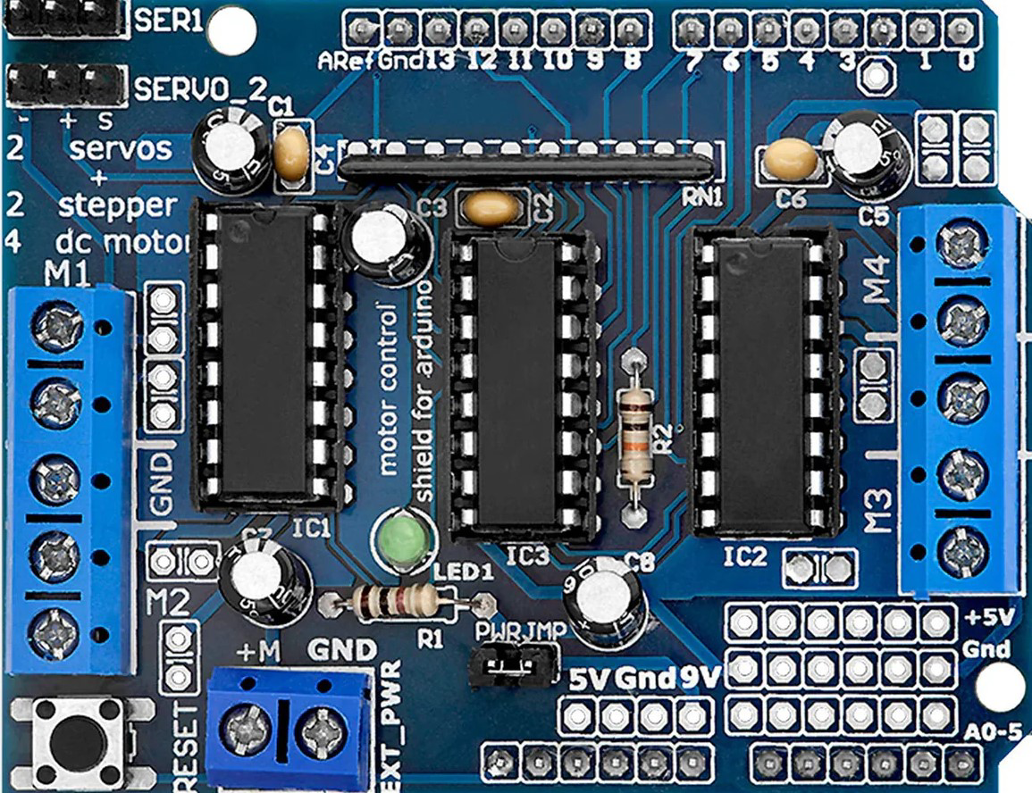
The L293D is a popular Motor Driver IC that allows a microcontroller like the Arduino to drive both DC and bipolar stepping motors. It consists of four half-H drivers, which can be used to drive inductive loads by providing bidirectional drive currents. This IC is widely used in robotics and small-scale automation projects due to its ability to control two DC motors simultaneously or one stepper motor.
Explore Projects Built with L293D
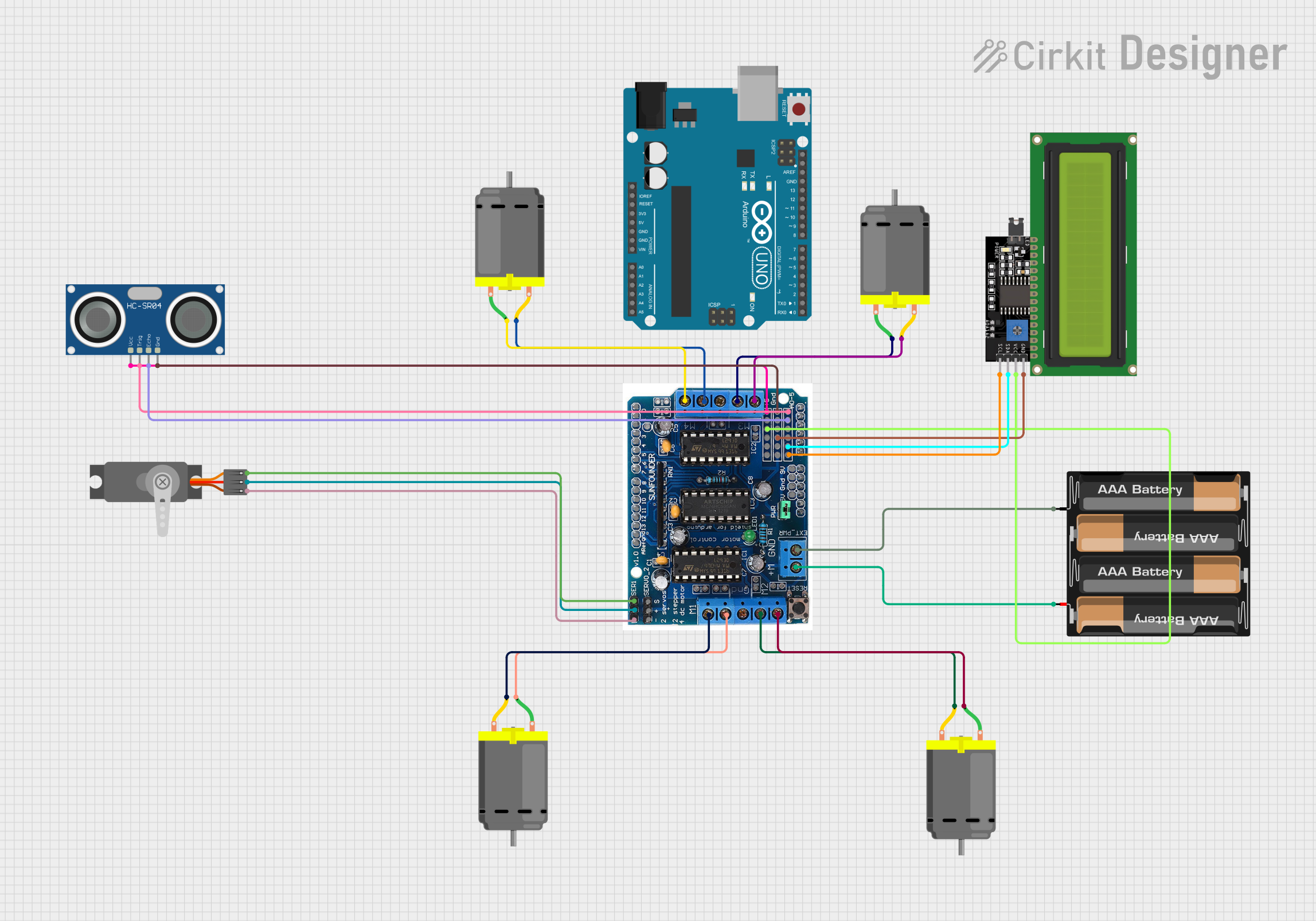

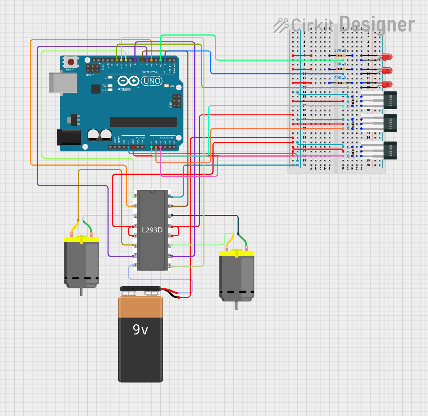
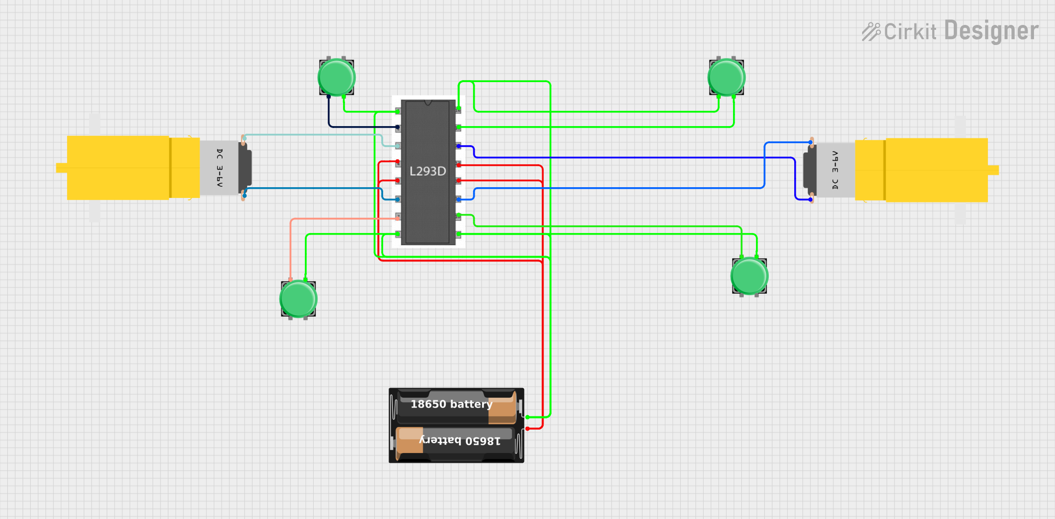
Explore Projects Built with L293D
Common Applications and Use Cases
- Driving DC motors in robotics
- Controlling bipolar stepper motors in 3D printers and CNC machines
- Operating relays and solenoids in automation systems
Technical Specifications
Key Technical Details
- Supply Voltage (Vcc1): 4.5V to 36V
- Supply Voltage for Logic (Vcc2): 4.5V to 7V
- Output Current (each channel): 600mA
- Peak Output Current (each channel): 1.2A
- Output Clamp Diodes for Inductive Transient Suppression
- Operating Temperature: -40°C to +150°C
Pin Configuration and Descriptions
| Pin Number | Name | Description |
|---|---|---|
| 1 | Enable 1,2 | Enables outputs for channels 1 and 2 when high |
| 2 | Input 1 | Logic input for channel 1 |
| 3 | Output 1 | Output for channel 1 |
| 4, 5 | Ground | Ground (0V) reference for the power stage |
| 6 | Output 2 | Output for channel 2 |
| 7 | Input 2 | Logic input for channel 2 |
| 8 | Vcc2 | Supply voltage for the logic circuitry |
| 9 | Enable 3,4 | Enables outputs for channels 3 and 4 when high |
| 10 | Input 3 | Logic input for channel 3 |
| 11 | Output 3 | Output for channel 3 |
| 12, 13 | Ground | Ground (0V) reference for the power stage |
| 14 | Output 4 | Output for channel 4 |
| 15 | Input 4 | Logic input for channel 4 |
| 16 | Vcc1 | Supply voltage for the power stage |
Usage Instructions
How to Use the L293D in a Circuit
- Connect Vcc1 to a suitable power supply (4.5V to 36V).
- Connect Vcc2 to the logic supply voltage (4.5V to 7V), which is typically the same as the microcontroller's operating voltage.
- Connect the grounds of the power supply, the L293D, and the microcontroller together.
- Connect the Enable pins to the microcontroller's digital output pins if you wish to control the enable function programmatically.
- Connect the Input pins to the microcontroller's digital output pins to control the direction of the motors.
- Connect the Output pins to the motor terminals.
- Use the Enable pins to turn the motor on or off, and the Input pins to control the direction.
Important Considerations and Best Practices
- Always use a separate power supply for Vcc1 when driving high-current loads to prevent damage to the microcontroller.
- Use flyback diodes if driving inductive loads to protect the L293D from voltage spikes.
- Ensure that the power supply can provide sufficient current for the motors.
- Avoid running the L293D at its maximum current rating for extended periods to prevent overheating.
Example Code for Arduino UNO
// Define the motor control pins
#define ENABLE_PIN 9
#define INPUT1_PIN 2
#define INPUT2_PIN 3

void setup() {
  // Set the motor control pins as outputs
  pinMode(ENABLE_PIN, OUTPUT);
  pinMode(INPUT1_PIN, OUTPUT);
  pinMode(INPUT2_PIN, OUTPUT);
}

void loop() {
  // Turn the motor on
  digitalWrite(ENABLE_PIN, HIGH);

  // Set the motor direction to forward
  digitalWrite(INPUT1_PIN, HIGH);
  digitalWrite(INPUT2_PIN, LOW);

  delay(2000); // Run the motor for 2 seconds

  // Set the motor direction to reverse
  digitalWrite(INPUT1_PIN, LOW);
  digitalWrite(INPUT2_PIN, HIGH);

  delay(2000); // Run the motor in reverse for 2 seconds

  // Turn the motor off
  digitalWrite(ENABLE_PIN, LOW);

  delay(1000); // Wait for 1 second
}
Troubleshooting and FAQs
Common Issues Users Might Face
- Motor not running: Check power supply connections, ensure the Enable pin is high, and verify that the Input pins are correctly configured.
- Motor running hot: This may be due to overloading the motor or the L293D. Check the current rating and reduce the load if necessary.
- Unexpected behavior: Ensure that the logic supply voltage (Vcc2) is within the specified range and that the ground connections are secure.
Solutions and Tips for Troubleshooting
- Use a multimeter to check for proper voltage levels at the power supply and the L293D pins.
- If the motor is not running, swap the connections at the Input pins to check if the motor direction control is working.
- Ensure that the Enable pin is connected and receiving the correct logic level to enable the motor driver.
FAQs
Q: Can I drive two motors simultaneously with one L293D? A: Yes, the L293D can drive two DC motors simultaneously, one connected to channels 1 and 2, and the other to channels 3 and 4.
Q: Do I need to use heat sinks with the L293D? A: It depends on the current your motors are drawing. If they are close to the maximum rating of 600mA per channel, using a heat sink is recommended.
Q: Can the L293D be used to drive servo motors? A: No, the L293D is not suitable for driving servo motors, which require a specific PWM signal for positioning. The L293D is designed for DC and stepper motors.