How to Use Adafruit 8x16 LED Matrix FeatherWing - Pure Green: Examples, Pinouts, and Specs
Introduction
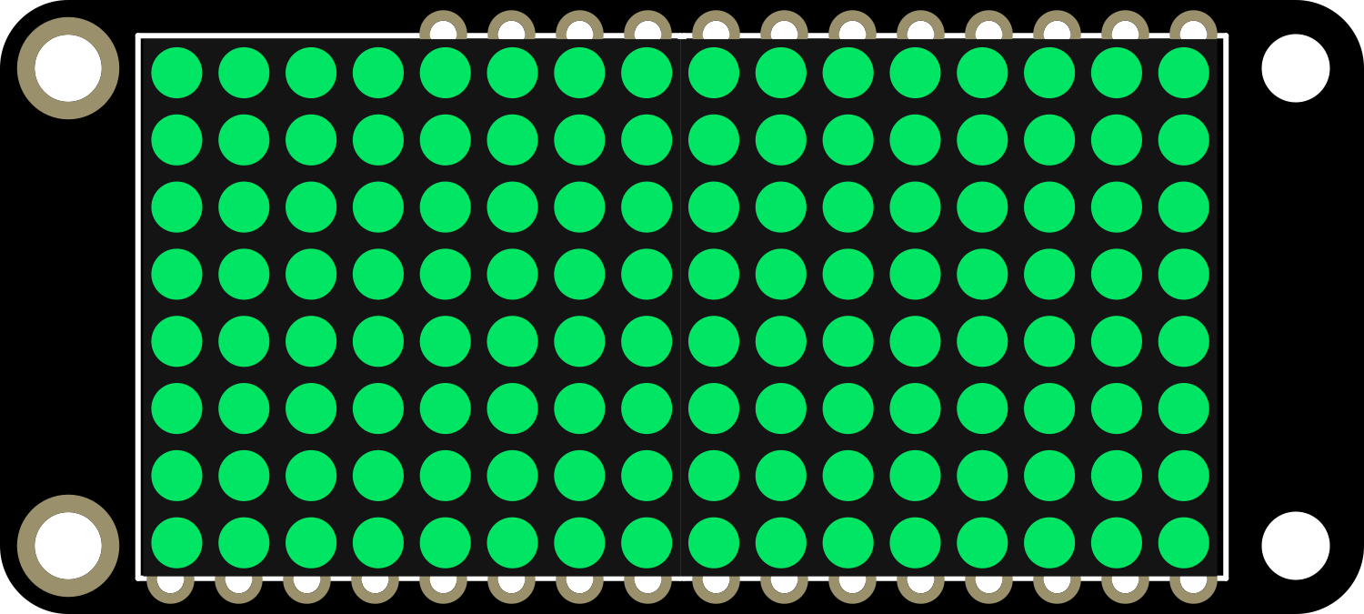
The Adafruit 8x16 LED Matrix FeatherWing in Pure Green is a versatile and compact electronic component designed to interface with the Adafruit Feather series of development boards. This LED matrix provides a grid of 8x16 (128) bright green LEDs, ideal for displaying scrolling text, animations, and simple graphics. It is perfect for wearable projects, badges, or any application where a small yet visible display is needed.
Explore Projects Built with Adafruit 8x16 LED Matrix FeatherWing - Pure Green
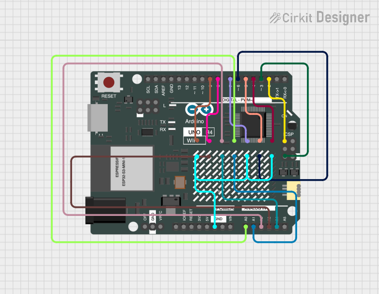


Explore Projects Built with Adafruit 8x16 LED Matrix FeatherWing - Pure Green
Common Applications and Use Cases
- Wearable electronics
- Name badges and signage
- Data visualization
- User interfaces for compact devices
- Educational projects and learning platforms
Technical Specifications
Key Technical Details
- LED Color: Pure Green
- Matrix Size: 8x16 LEDs
- Operating Voltage: 3.3V to 5V DC
- Communication Interface: I2C
- I2C Addresses: 0x70 (default), selectable with solder jumpers
Pin Configuration and Descriptions
| Pin | Description |
|---|---|
| GND | Ground connection |
| 3V | 3.3V power supply |
| SDA | I2C data line |
| SCL | I2C clock line |
| RST | Reset pin (optional use) |
| A0 | Address selection pin 0 |
| A1 | Address selection pin 1 |
| A2 | Address selection pin 2 |
| A3 | Address selection pin 3 |
| A4 | Address selection pin 4 |
| A5 | Address selection pin 5 |
Usage Instructions
How to Use the Component in a Circuit
- Powering the Matrix: Connect the 3V and GND pins to the corresponding power supply pins on your Feather board.
- I2C Communication: Connect the SDA and SCL pins to the I2C data and clock lines on your Feather board.
- Address Selection: If using multiple LED matrices, solder the address selection pins (A0-A5) to set unique I2C addresses for each matrix.
- Software Initialization: Use the Adafruit LED Backpack library to control the matrix via I2C.
Important Considerations and Best Practices
- Ensure that the power supply is within the operating voltage range.
- When daisy-chaining multiple matrices, calculate the total current draw to avoid overloading the power supply.
- Use pull-up resistors on the I2C lines if they are not included on the Feather board.
- Avoid exposing the matrix to mechanical stress or moisture.
Example Code for Arduino UNO
#include <Wire.h>
#include <Adafruit_GFX.h>
#include <Adafruit_LEDBackpack.h>

Adafruit_8x16matrix matrix = Adafruit_8x16matrix();

void setup() {
  matrix.begin(0x70); // Initialize the matrix with its I2C address
  matrix.setBrightness(10); // Set brightness level (0 is dim, 15 is bright)
}

void loop() {
  matrix.clear(); // Clear the matrix display
  matrix.setCursor(0, 0); // Set cursor at top-left corner
  matrix.print("Hello"); // Print a message
  matrix.writeDisplay(); // Update the display with the new data
  delay(2000); // Wait for 2 seconds
}
Troubleshooting and FAQs
Common Issues
- LEDs Not Lighting Up: Ensure that the matrix is properly powered and that the I2C lines are correctly connected.
- Garbled Display: Check for correct I2C address and ensure there are no conflicts with other I2C devices.
- Dim Display: Adjust the brightness setting in your code or check the power supply voltage.
Solutions and Tips for Troubleshooting
- Double-check wiring connections and solder joints for any loose connections or shorts.
- Use the
i2cdetectutility or similar tools to confirm the matrix's I2C address. - If using multiple matrices, ensure that each has a unique I2C address.
FAQs
Q: Can I use this matrix with a 5V system? A: Yes, the matrix can operate on a 3.3V to 5V power supply.
Q: How do I change the I2C address? A: Solder the address selection pins (A0-A5) to set a unique address for each matrix.
Q: Can I chain multiple matrices together? A: Yes, you can chain multiple matrices by connecting their I2C lines together and setting unique addresses for each.
Q: Is there a library available for controlling the matrix? A: Yes, the Adafruit LED Backpack library is available for easy control of the matrix.
For further assistance, consult the Adafruit forums or the detailed product guide available on the Adafruit website.