How to Use DC Motor with Encoder: Examples, Pinouts, and Specs
Introduction
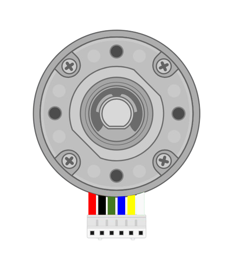
The Pololu 29-to-1 Gear Motor With Encoder is a high-performance DC motor integrated with a quadrature encoder. This motor is equipped with a 29:1 metal gearbox, providing high torque and low-speed operation, making it ideal for applications requiring precise control. The built-in encoder outputs signals that allow users to monitor the motor's position, speed, and direction, enabling closed-loop control systems.
Explore Projects Built with DC Motor with Encoder

Explore Projects Built with DC Motor with Encoder
Common Applications
- Robotics (e.g., robotic arms, mobile robots)
- Automated systems and conveyors
- Precision motion control
- Motorized camera sliders
- CNC machines and 3D printers
Technical Specifications
Below are the key technical details for the Pololu 29-to-1 Gear Motor With Encoder:
| Parameter | Value |
|---|---|
| Operating Voltage | 6 V to 12 V |
| Gear Ratio | 29:1 |
| Free-run Speed @ 12V | ~490 RPM |
| Free-run Current @ 12V | ~300 mA |
| Stall Torque @ 12V | ~2.3 kg·cm |
| Stall Current @ 12V | ~5 A |
| Encoder Resolution | 64 counts per revolution of the motor shaft (before gearbox) |
| Output Shaft Diameter | 4 mm |
| Motor Dimensions | 37D x 57L mm |
| Weight | ~190 g |
Pin Configuration and Descriptions
The motor has six wires: two for the motor power and four for the encoder signals. The pinout is as follows:
| Wire Color | Function | Description |
|---|---|---|
| Red | Motor Power (+) | Connect to the positive terminal of the power supply. |
| Black | Motor Power (-) | Connect to the negative terminal of the power supply. |
| Green | Encoder Channel A | Outputs a quadrature signal for position/speed feedback. |
| Blue | Encoder Channel B | Outputs a quadrature signal for position/speed feedback. |
| Yellow | Encoder Power (+) | Connect to a 3.3V or 5V power source for the encoder. |
| White | Encoder Ground (-) | Connect to the ground of the encoder power source. |
Usage Instructions
How to Use the Component in a Circuit
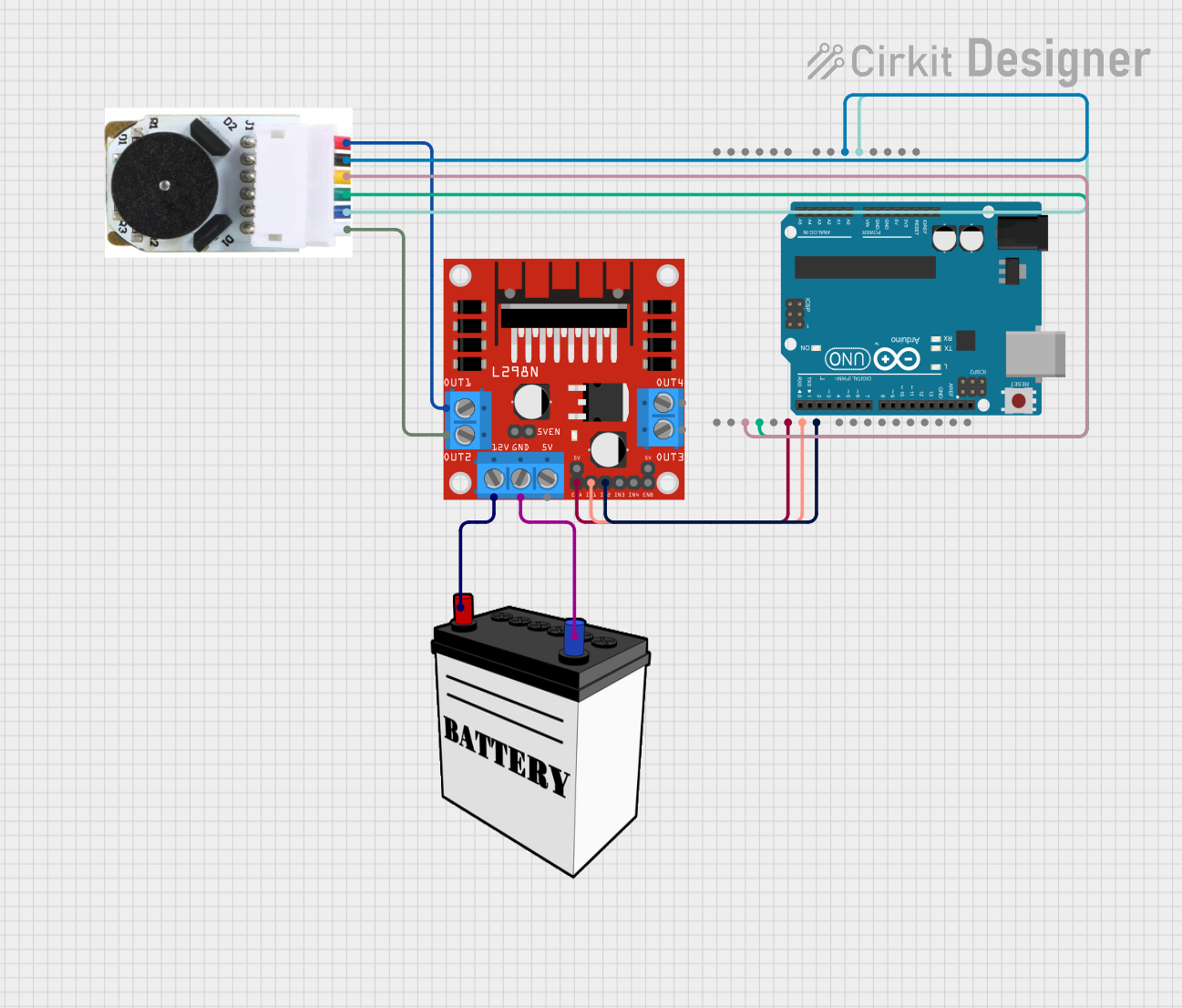
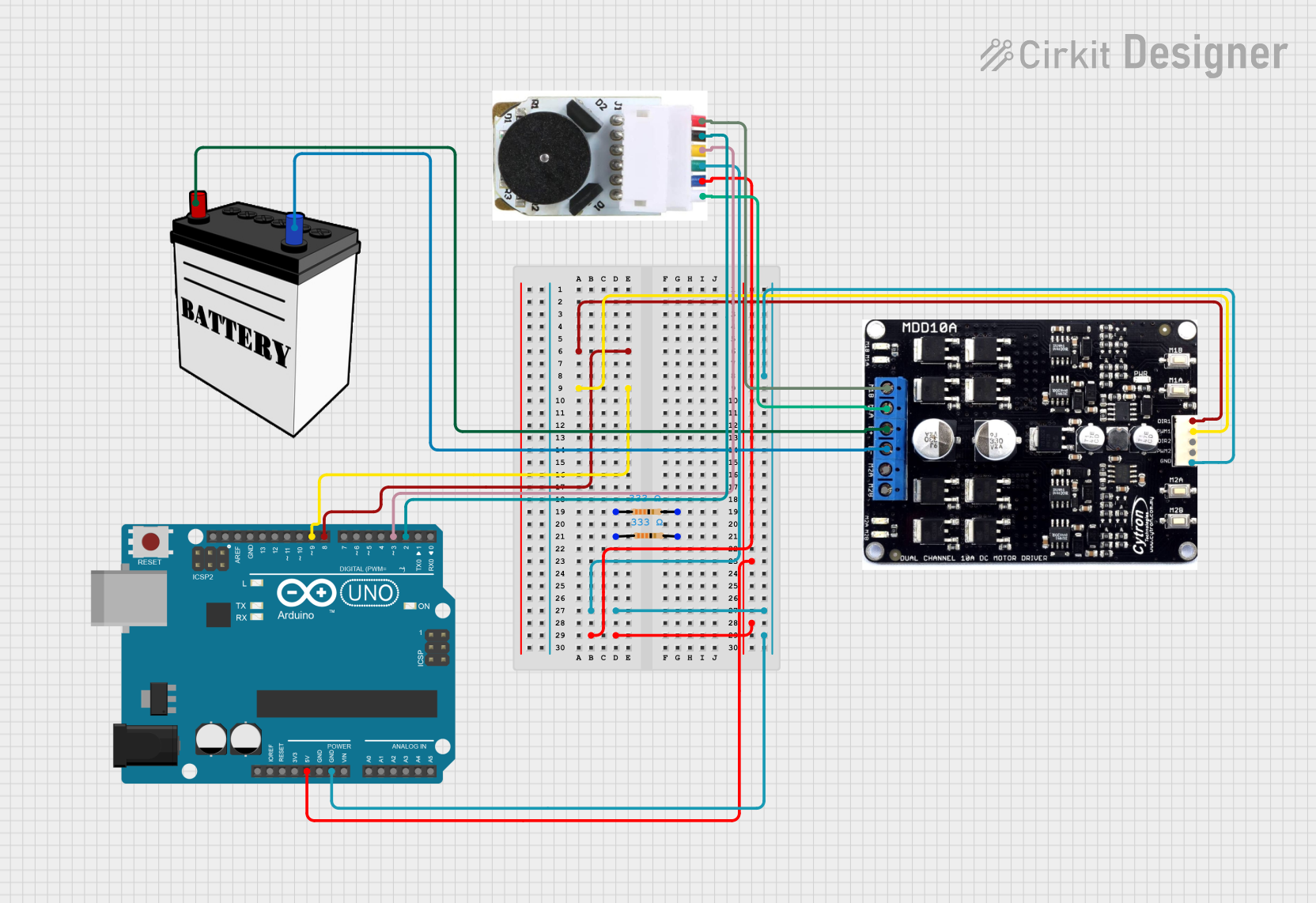
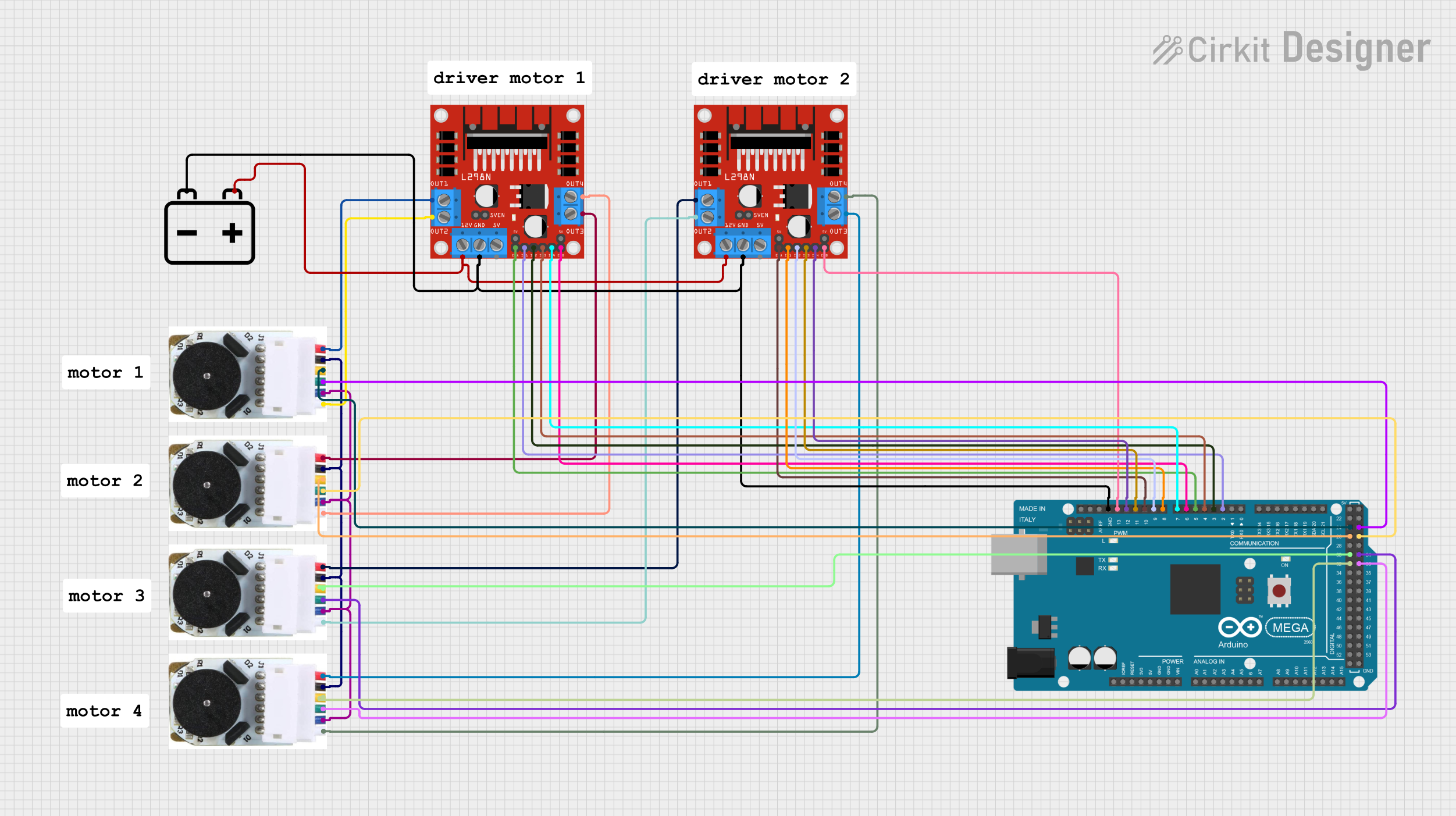
Powering the Motor:
- Connect the red and black wires to a motor driver or H-bridge circuit capable of handling the motor's voltage and current requirements.
- Ensure the power supply can provide sufficient current, especially during stall conditions (up to 5 A).
Connecting the Encoder:
- Supply 3.3V or 5V to the yellow wire (encoder power) and connect the white wire to ground.
- Connect the green and blue wires (encoder channels A and B) to the input pins of a microcontroller or encoder interface. These signals provide quadrature feedback.
Controlling the Motor:
- Use a motor driver or H-bridge to control the motor's speed and direction. Pulse Width Modulation (PWM) can be used for speed control.
- Read the encoder signals to monitor the motor's position and speed.
Important Considerations and Best Practices
- Power Supply: Use a power supply that can handle the motor's stall current to avoid voltage drops or damage.
- Motor Driver: Select a motor driver that supports the motor's voltage and current ratings. For example, Pololu's VNH5019 motor driver is a good choice.
- Encoder Signal Handling: Use interrupt pins on your microcontroller to accurately read the encoder signals, especially at high speeds.
- Decoupling Capacitors: Add capacitors across the motor terminals to reduce electrical noise that could interfere with the encoder signals.
- Mounting: Securely mount the motor to prevent vibrations that could affect performance.
Example Code for Arduino UNO
Below is an example of how to read the encoder signals and control the motor using an Arduino UNO:
// Define encoder pins
const int encoderA = 2; // Encoder Channel A connected to pin 2 (interrupt pin)
const int encoderB = 3; // Encoder Channel B connected to pin 3

// Define motor control pins
const int motorPWM = 9;  // PWM pin for motor speed control
const int motorDir = 8;  // Digital pin for motor direction control

volatile long encoderCount = 0; // Variable to store encoder counts

// Interrupt service routine for encoder channel A
void encoderISR() {
  // Read the state of channel B to determine direction
  if (digitalRead(encoderB) == HIGH) {
    encoderCount++; // Forward direction
  } else {
    encoderCount--; // Reverse direction
  }
}

void setup() {
  // Initialize serial communication
  Serial.begin(9600);

  // Set up encoder pins
  pinMode(encoderA, INPUT_PULLUP);
  pinMode(encoderB, INPUT_PULLUP);

  // Attach interrupt to encoder channel A
  attachInterrupt(digitalPinToInterrupt(encoderA), encoderISR, CHANGE);

  // Set up motor control pins
  pinMode(motorPWM, OUTPUT);
  pinMode(motorDir, OUTPUT);

  // Start motor at low speed
  analogWrite(motorPWM, 128); // 50% duty cycle
  digitalWrite(motorDir, HIGH); // Set direction to forward
}

void loop() {
  // Print encoder count to the serial monitor
  Serial.print("Encoder Count: ");
  Serial.println(encoderCount);

  delay(100); // Small delay for readability
}
Notes on the Code
- The encoder ISR (Interrupt Service Routine) ensures accurate counting of encoder pulses.
- The motor's speed is controlled using PWM, and the direction is set using a digital pin.
- Adjust the
analogWritevalue to change the motor speed.
Troubleshooting and FAQs
Common Issues and Solutions
Motor Not Spinning:
- Check the power supply and ensure it meets the motor's voltage and current requirements.
- Verify the motor driver connections and ensure the driver is functioning correctly.
Encoder Signals Not Detected:
- Ensure the encoder power (yellow wire) is connected to a 3.3V or 5V source.
- Check the connections to the microcontroller and ensure the correct pins are used.
- Verify that the encoder wires are not swapped.
Noisy Encoder Readings:
- Add decoupling capacitors (e.g., 0.1 µF) across the motor terminals to reduce electrical noise.
- Use shielded cables for the encoder wires if operating in a noisy environment.
Motor Overheating:
- Avoid running the motor at stall conditions for extended periods.
- Ensure proper ventilation and avoid overloading the motor.
FAQs
Q: Can I use this motor with a 24V power supply?
A: No, the motor is designed for a maximum voltage of 12V. Using a higher voltage may damage the motor.
Q: How do I calculate the motor's position in degrees?
A: Use the formula:
Position (degrees) = (Encoder Count / Encoder Resolution) * 360 / Gear Ratio
For this motor, the encoder resolution is 64 counts per revolution of the motor shaft.
Q: Can I use this motor with a Raspberry Pi?
A: Yes, but you will need a motor driver compatible with the Raspberry Pi's GPIO voltage levels and a library to handle encoder signals.
Q: What is the maximum speed of the motor?
A: The free-run speed at 12V is approximately 490 RPM at the output shaft.