
How to Use Optocoupler Isolation Module 24V to 5V: Examples, Pinouts, and Specs
 Design with Optocoupler Isolation Module 24V to 5V in Cirkit Designer
Introduction
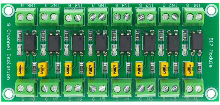
The Optocoupler Isolation Module 24V to 5V is a device designed to provide electrical isolation between two circuits operating at different voltage levels. It uses an optocoupler to transmit signals optically, ensuring that there is no direct electrical connection between the high-voltage (24V) and low-voltage (5V) sides. This isolation protects sensitive components in the low-voltage circuit from potential damage caused by voltage spikes or noise in the high-voltage circuit.
Explore Projects Built with Optocoupler Isolation Module 24V to 5V
 Open Project in Cirkit Designer
 Open Project in Cirkit Designer
 Open Project in Cirkit Designer
 Open Project in Cirkit Designer
Explore Projects Built with Optocoupler Isolation Module 24V to 5V
Open Project in Cirkit DesignerOpen Project in Cirkit DesignerOpen Project in Cirkit DesignerOpen Project in Cirkit DesignerCommon Applications and Use Cases
- Industrial automation systems for isolating control signals.
- Microcontroller-based projects requiring safe interfacing with high-voltage devices.
- Protection of low-voltage circuits from electrical noise or surges.
- Signal level shifting between 24V and 5V systems.
- Motor control circuits and power supply monitoring.
Technical Specifications
Key Technical Details
- Input Voltage (High Side): 24V DC
- Output Voltage (Low Side): 5V DC
- Isolation Voltage: Up to 2500V
- Signal Transmission Type: Optical (via optocoupler)
- Input Signal Current: 5-20mA (typical)
- Output Signal Type: Digital (High/Low)
- Response Time: < 10 µs
- Operating Temperature Range: -40°C to 85°C
- PCB Dimensions: 40mm x 20mm x 10mm (approx.)
Pin Configuration and Descriptions
High-Voltage Side (Input)
| Pin Name | Description |
|---|---|
| VCC | Connect to 24V DC power supply. |
| IN | Input signal (24V logic level). |
| GND | Ground connection for 24V circuit. |
Low-Voltage Side (Output)
| Pin Name | Description |
|---|---|
| VCC | Connect to 5V DC power supply. |
| OUT | Output signal (5V logic level). |
| GND | Ground connection for 5V circuit. |
Usage Instructions
How to Use the Component in a Circuit
Power Connections:
- Connect the high-voltage side's
VCCpin to a 24V DC power source and itsGNDpin to the ground of the 24V circuit. - Connect the low-voltage side's
VCCpin to a 5V DC power source and itsGNDpin to the ground of the 5V circuit.
- Connect the high-voltage side's
Signal Connections:
- Feed the input signal (24V logic level) to the
INpin on the high-voltage side. - The optocoupler will isolate and transmit the signal to the low-voltage side, where it will appear as a 5V logic level on the
OUTpin.
- Feed the input signal (24V logic level) to the
Load Connection:
- Connect the
OUTpin to the input of the low-voltage circuit or microcontroller to process the signal.
- Connect the
Important Considerations and Best Practices
- Ensure that the
GNDconnections of the high-voltage and low-voltage sides are not directly connected to maintain proper isolation. - Verify that the input signal current is within the specified range (5-20mA) to avoid damaging the optocoupler.
- Use decoupling capacitors (e.g., 0.1µF) near the power supply pins to reduce noise and improve stability.
- Avoid exceeding the isolation voltage rating (2500V) to prevent damage to the module.
- For high-speed signals, ensure that the response time (< 10 µs) is suitable for your application.
Example: Connecting to an Arduino UNO
The module can be used to safely interface a 24V signal with an Arduino UNO. Below is an example code snippet:
// Example code for reading a signal from the Optocoupler Isolation Module
// and controlling an LED based on the signal state.

const int optoInputPin = 2;  // Arduino pin connected to the module's OUT pin
const int ledPin = 13;       // Arduino built-in LED pin

void setup() {
  pinMode(optoInputPin, INPUT);  // Set the optocoupler output pin as input
  pinMode(ledPin, OUTPUT);       // Set the LED pin as output
  digitalWrite(ledPin, LOW);     // Turn off the LED initially
  Serial.begin(9600);            // Initialize serial communication
}

void loop() {
  int signalState = digitalRead(optoInputPin);  // Read the signal state

  if (signalState == HIGH) {
    digitalWrite(ledPin, HIGH);  // Turn on the LED if signal is HIGH
    Serial.println("Signal HIGH: LED ON");
  } else {
    digitalWrite(ledPin, LOW);   // Turn off the LED if signal is LOW
    Serial.println("Signal LOW: LED OFF");
  }

  delay(100);  // Small delay for stability
}
Troubleshooting and FAQs
Common Issues and Solutions
No Output Signal on the Low-Voltage Side:
- Cause: Incorrect wiring or insufficient input current.
- Solution: Double-check the wiring and ensure the input signal current is within the 5-20mA range.
Output Signal is Unstable or Noisy:
- Cause: Power supply noise or insufficient decoupling.
- Solution: Add decoupling capacitors (e.g., 0.1µF) near the power supply pins.
Loss of Isolation:
- Cause: Ground connections of the high-voltage and low-voltage sides are connected.
- Solution: Ensure that the grounds of the two sides are electrically isolated.
Module Overheating:
- Cause: Input voltage or current exceeds the specified limits.
- Solution: Verify that the input voltage is 24V and the input current is within the specified range.
FAQs
Q1: Can this module handle AC signals?
A1: No, this module is designed for DC signals only. For AC signal isolation, use a specialized optocoupler module.
Q2: What is the maximum frequency of the input signal?
A2: The module can handle signals with frequencies up to approximately 100 kHz, depending on the optocoupler's response time.
Q3: Can I use this module with a 12V input instead of 24V?
A3: Yes, the module can work with lower input voltages (e.g., 12V), but ensure the input current is sufficient to drive the optocoupler.
Q4: Is the module compatible with 3.3V systems?
A4: The output signal is 5V logic level. Use a level shifter if interfacing with 3.3V systems.