How to Use UV Sensor: Examples, Pinouts, and Specs
Introduction
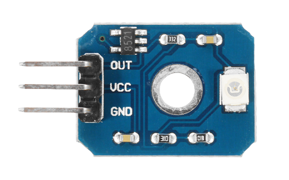
A UV sensor is an electronic device designed to measure the intensity of ultraviolet (UV) light, which is a type of electromagnetic radiation with a wavelength shorter than that of visible light but longer than X-rays. UV sensors are commonly used in applications such as monitoring sunlight exposure, testing for UV sterilization, and in weather stations to measure the UV index. They can also be found in various consumer products, such as wearable UV exposure trackers and smart home systems.
Explore Projects Built with UV Sensor
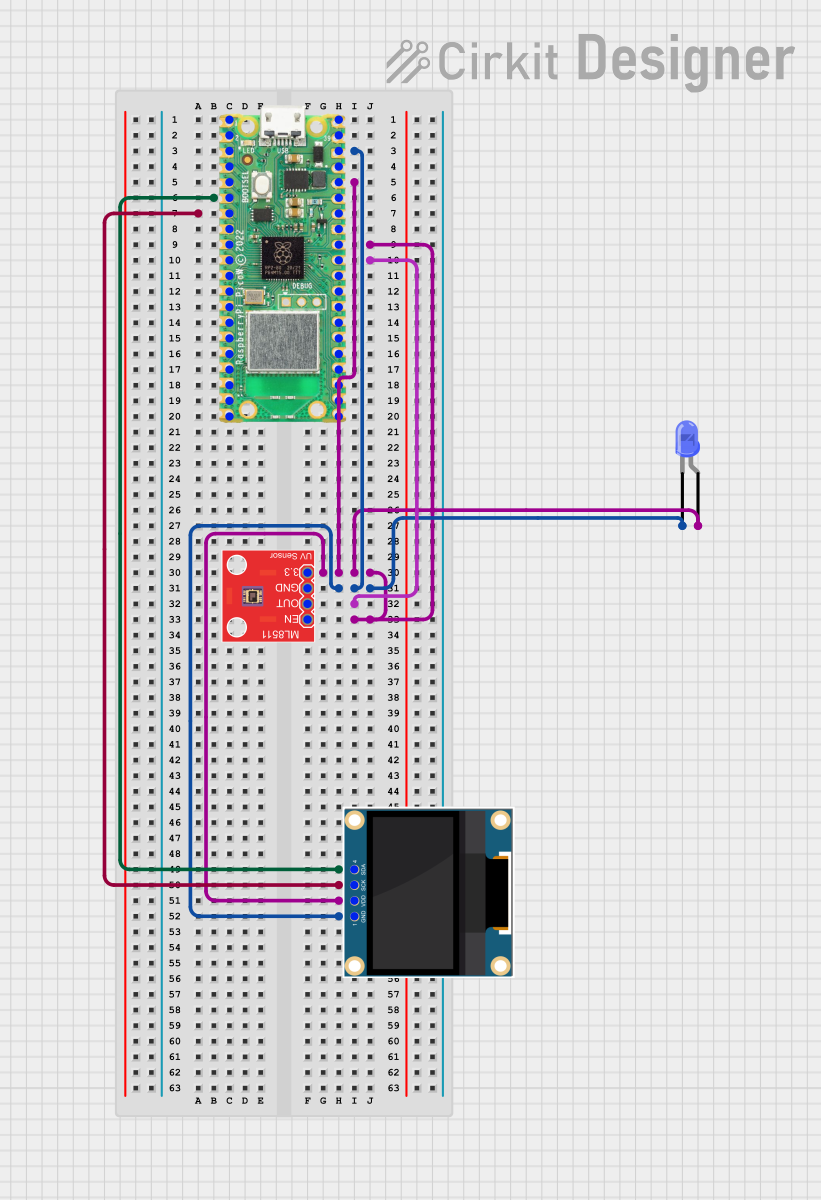
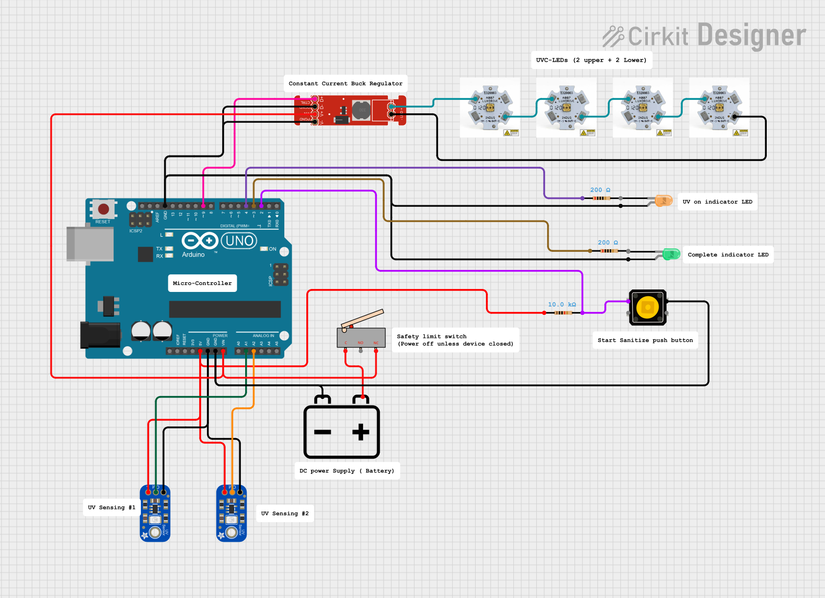
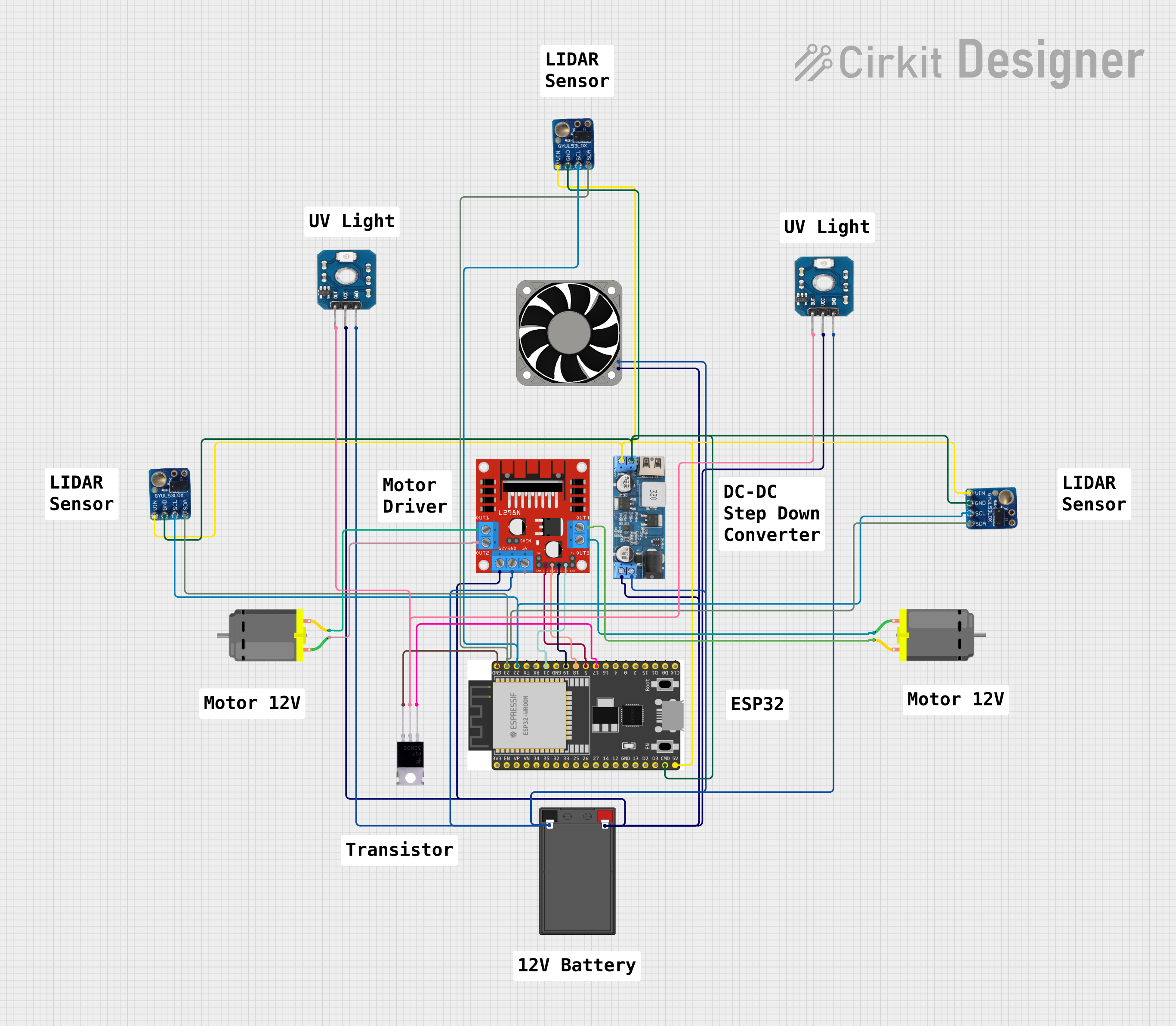

Explore Projects Built with UV Sensor
Technical Specifications
Key Technical Details
- Spectral Response Range: Typically from 200 nm to 400 nm, covering UVA, UVB, and sometimes UVC ranges.
- Output Type: Analog voltage, PWM, or digital (I2C, SPI).
- Supply Voltage: Commonly 3.3V to 5V.
- Operating Temperature: Range can vary, often from -20°C to +85°C.
Pin Configuration and Descriptions
| Pin Number | Name | Description |
|---|---|---|
| 1 | VCC | Power supply (3.3V - 5V) |
| 2 | GND | Ground connection |
| 3 | OUT | Analog or digital output signal |
| 4 | EN | Enable pin (optional, not present on all models) |
Usage Instructions
Integration with a Circuit
To use the UV sensor in a circuit:
- Connect the VCC pin to a power supply within the sensor's rated voltage.
- Attach the GND pin to the common ground in the circuit.
- Connect the OUT pin to an analog input on a microcontroller for analog sensors, or to the appropriate communication pins for digital sensors (I2C/SPI).
- If present, the EN pin can be connected to a digital output on a microcontroller to enable or disable the sensor.
Best Practices
- Calibration: Some UV sensors may require calibration with a known UV light source to ensure accurate readings.
- Shielding: Protect the sensor from exposure to harsh environmental conditions and direct sunlight when not in use.
- Orientation: For accurate readings, ensure the sensor's photodiode is correctly oriented towards the UV light source.
Example Code for Arduino UNO
// Example code for interfacing a UV sensor with an Arduino UNO
int uvSensorPin = A0; // Connect the sensor output to A0
int uvLevel;

void setup() {
  Serial.begin(9600);
}

void loop() {
  uvLevel = analogRead(uvSensorPin); // Read the UV intensity
  float voltage = uvLevel * (5.0 / 1023.0); // Convert to voltage
  Serial.print("UV Level (Voltage): ");
  Serial.println(voltage);
  delay(1000); // Wait for 1 second before the next read
}
Troubleshooting and FAQs
Common Issues
- Inaccurate Readings: Ensure the sensor is not obstructed and is properly calibrated.
- No Output Signal: Check the power supply and connections to the sensor.
- Erratic Readings: Verify that the sensor is not exposed to rapid changes in light intensity or temperature.
Solutions and Tips
- Calibration: Use a reference UV light source to calibrate the sensor periodically.
- Connections: Ensure all connections are secure and free from corrosion or damage.
- Shielding: Use a UV-transparent cover to protect the sensor from the elements while allowing UV light to pass through.
FAQs
Q: Can the UV sensor detect UVC light? A: It depends on the sensor's spectral response range. Check the manufacturer's specifications.
Q: How do I know if my sensor requires calibration? A: Refer to the sensor's datasheet or contact the manufacturer for calibration information.
Q: Can I use the UV sensor with a 3.3V system? A: Yes, if the sensor's rated voltage includes 3.3V. Always check the technical specifications.
Q: What is the lifespan of a UV sensor? A: The lifespan can vary based on usage and environmental conditions. Consult the manufacturer's documentation for more information.
Remember to always refer to the specific datasheet of the UV sensor model you are using for the most accurate and detailed information.