How to Use IRF3205: Examples, Pinouts, and Specs
Introduction
The IRF3205 is an N-channel MOSFET manufactured by International Rectifier (Part ID: IRF). It is designed for high-speed switching applications and offers low on-resistance (RDS(on)) and high current handling capabilities. These features make it ideal for use in power management, motor control circuits, DC-DC converters, and other high-efficiency switching applications.
Explore Projects Built with IRF3205


Explore Projects Built with IRF3205
Common Applications
- Motor drivers for robotics and industrial automation
- DC-DC converters in power supply systems
- Battery management systems
- High-current switching in automotive electronics
- Inverters for renewable energy systems
Technical Specifications
The IRF3205 is a robust and efficient MOSFET with the following key specifications:
| Parameter | Value |
|---|---|
| Type | N-Channel MOSFET |
| Maximum Drain-Source Voltage (VDS) | 55V |
| Maximum Gate-Source Voltage (VGS) | ±20V |
| Continuous Drain Current (ID) @ 25°C | 110A |
| Pulsed Drain Current (IDM) | 390A |
| Maximum Power Dissipation (PD) | 200W |
| RDS(on) (at VGS = 10V, ID = 75A) | 8 mΩ |
| Gate Threshold Voltage (VGS(th)) | 2.0V - 4.0V |
| Operating Temperature Range | -55°C to +175°C |
| Package Type | TO-220 |
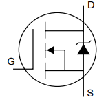
Pin Configuration
The IRF3205 is typically available in a TO-220 package with three pins. The pinout is as follows:
| Pin Number | Pin Name | Description |
|---|---|---|
| 1 | Gate (G) | Controls the MOSFET switching state |
| 2 | Drain (D) | Current flows from drain to source |
| 3 | Source (S) | Connected to ground or load return |
Usage Instructions
The IRF3205 is straightforward to use in a variety of circuits. Below are the steps and considerations for proper usage:
How to Use the IRF3205 in a Circuit
Gate Control:
- Apply a voltage between the Gate (G) and Source (S) to control the MOSFET. A voltage of 10V is recommended for full enhancement and minimal RDS(on).
- Use a gate resistor (e.g., 10Ω) to limit inrush current and prevent damage to the gate.
Drain-Source Connection:
- Connect the load between the Drain (D) and the positive supply voltage.
- Ensure the Source (S) is connected to ground or the return path of the circuit.
Heat Dissipation:
- Use a heatsink with the TO-220 package to manage heat dissipation, especially in high-current applications.
Protection:
- Add a flyback diode across inductive loads (e.g., motors) to protect the MOSFET from voltage spikes.
- Use a zener diode or TVS diode to protect the Gate from voltage surges exceeding ±20V.
Example: Using the IRF3205 with an Arduino UNO
The IRF3205 can be controlled by an Arduino UNO for switching applications. Below is an example of controlling a DC motor:
Circuit Connections
- Gate (G): Connect to an Arduino digital pin (e.g., D9) through a 220Ω resistor.
- Drain (D): Connect to one terminal of the motor.
- Source (S): Connect to ground.
- Motor: Connect the other terminal to the positive supply voltage.
- Flyback Diode: Place a diode (e.g., 1N4007) across the motor terminals to protect against voltage spikes.
Arduino Code
// Example: Controlling a DC motor with IRF3205 and Arduino UNO

const int motorPin = 9; // Pin connected to the Gate of IRF3205

void setup() {
  pinMode(motorPin, OUTPUT); // Set motorPin as an output
}

void loop() {
  digitalWrite(motorPin, HIGH); // Turn the motor ON
  delay(2000);                 // Keep the motor ON for 2 seconds
  digitalWrite(motorPin, LOW);  // Turn the motor OFF
  delay(2000);                 // Keep the motor OFF for 2 seconds
}
Best Practices
- Always ensure the Gate voltage is within the specified range (±20V).
- Use a proper heatsink to prevent overheating during high-power operation.
- Avoid exceeding the maximum ratings for voltage, current, and power dissipation.
Troubleshooting and FAQs
Common Issues and Solutions
MOSFET Overheating:
- Cause: Insufficient heatsinking or excessive current.
- Solution: Use a larger heatsink or reduce the load current.
MOSFET Not Switching:
- Cause: Insufficient Gate voltage.
- Solution: Ensure the Gate voltage is at least 10V for full enhancement.
Voltage Spikes Damaging the MOSFET:
- Cause: Inductive loads generating back EMF.
- Solution: Add a flyback diode across the load.
Gate Damage:
- Cause: Voltage spikes exceeding ±20V.
- Solution: Use a zener diode or TVS diode to protect the Gate.
FAQs
Q1: Can the IRF3205 be driven directly by a 5V microcontroller?
A1: While the IRF3205 can operate with a Gate voltage as low as 4V, it is recommended to use a Gate driver or a logic-level MOSFET for optimal performance when working with 5V logic.
Q2: What is the maximum current the IRF3205 can handle?
A2: The IRF3205 can handle up to 110A continuously at 25°C, but this requires proper heatsinking and thermal management.
Q3: Can the IRF3205 be used for AC switching?
A3: The IRF3205 is designed for DC applications. For AC switching, consider using a TRIAC or an IGBT.
Q4: How do I calculate the power dissipation of the IRF3205?
A4: Power dissipation can be calculated using the formula:
P = ID² × RDS(on).
For example, at ID = 50A and RDS(on) = 8mΩ, P = 50² × 0.008 = 20W.
By following these guidelines and best practices, the IRF3205 can be effectively used in a wide range of high-power applications.