How to Use lora hc 15: Examples, Pinouts, and Specs
Introduction
The LoRa HC 15 is a long-range, low-power wireless communication module that operates on the LoRa (Long Range) protocol. It is designed to enable devices to communicate over distances of several kilometers while consuming minimal power. This makes it an excellent choice for Internet of Things (IoT) applications, where energy efficiency and reliable communication are critical.
Explore Projects Built with lora hc 15
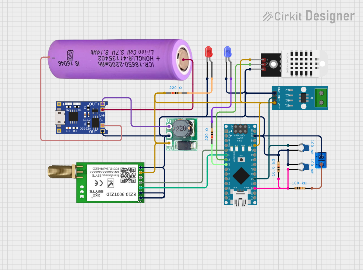

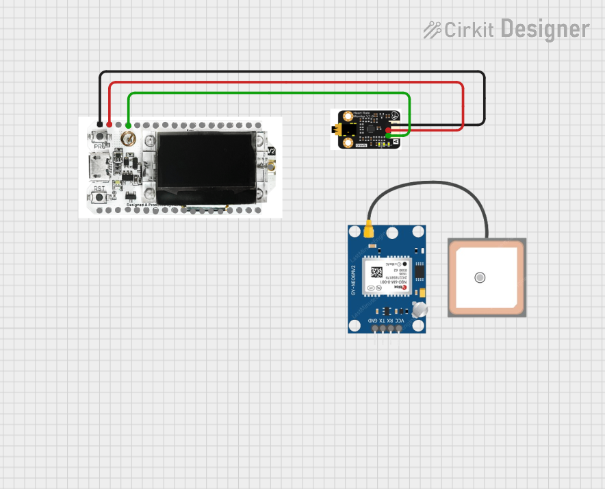

Explore Projects Built with lora hc 15
Common Applications and Use Cases
- Smart agriculture (e.g., soil moisture monitoring, weather stations)
- Industrial automation and monitoring
- Smart cities (e.g., parking sensors, streetlight control)
- Asset tracking and logistics
- Environmental monitoring (e.g., air quality sensors, water level monitoring)
Technical Specifications
The LoRa HC 15 module is built to provide robust and efficient communication. Below are its key technical details:
General Specifications
| Parameter | Value |
|---|---|
| Communication Protocol | LoRa (Long Range) |
| Frequency Range | 433 MHz / 868 MHz / 915 MHz |
| Transmission Power | Up to 20 dBm (100 mW) |
| Sensitivity | -137 dBm |
| Data Rate | 0.3 kbps to 50 kbps |
| Operating Voltage | 3.3V to 5V |
| Current Consumption | < 10 µA (sleep mode) |
| Operating Temperature | -40°C to +85°C |
| Communication Range | Up to 10 km (line of sight) |
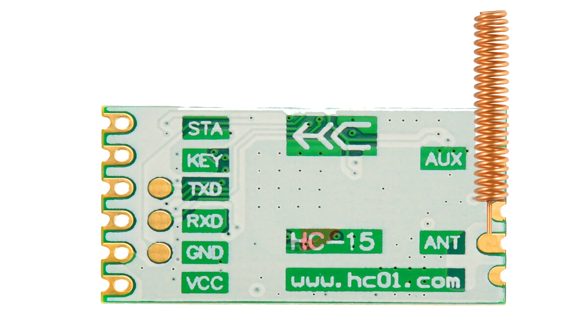
Pin Configuration and Descriptions
The LoRa HC 15 module typically has a 6-pin interface. Below is the pinout and description:
| Pin Number | Pin Name | Description |
|---|---|---|
| 1 | VCC | Power supply input (3.3V to 5V) |
| 2 | GND | Ground connection |
| 3 | TXD | UART Transmit pin (connect to RX of microcontroller) |
| 4 | RXD | UART Receive pin (connect to TX of microcontroller) |
| 5 | AUX | Auxiliary pin for status indication |
| 6 | SET | Configuration mode control pin |
Usage Instructions
The LoRa HC 15 module is straightforward to use in a circuit. Below are the steps and best practices for integrating it into your project:
Connecting the Module
- Power Supply: Connect the
VCCpin to a 3.3V or 5V power source and theGNDpin to ground. - UART Communication: Connect the
TXDpin of the module to theRXpin of your microcontroller, and theRXDpin of the module to theTXpin of your microcontroller. - Configuration Mode: Use the
SETpin to toggle between normal operation mode and configuration mode:- Pull
SETlow to enter configuration mode. - Leave
SEThigh (or unconnected) for normal operation.
- Pull
- Status Monitoring: Optionally, connect the
AUXpin to monitor the module's status.
Example: Using LoRa HC 15 with Arduino UNO
Below is an example of how to use the LoRa HC 15 module with an Arduino UNO for basic communication:
Circuit Diagram
- Connect
VCCto the 5V pin on the Arduino. - Connect
GNDto the GND pin on the Arduino. - Connect
TXDto pin 10 (software serial RX) on the Arduino. - Connect
RXDto pin 11 (software serial TX) on the Arduino.
Arduino Code
#include <SoftwareSerial.h>

// Define software serial pins for LoRa HC 15
SoftwareSerial loraSerial(10, 11); // RX = 10, TX = 11

void setup() {
  // Initialize serial communication
  Serial.begin(9600); // For debugging via Serial Monitor
  loraSerial.begin(9600); // LoRa HC 15 default baud rate

  Serial.println("LoRa HC 15 Module Test");
  delay(1000);
}

void loop() {
  // Send data to LoRa HC 15
  loraSerial.println("Hello, LoRa!");
  Serial.println("Message sent: Hello, LoRa!");

  // Check for incoming data from LoRa HC 15
  if (loraSerial.available()) {
    String receivedData = loraSerial.readString();
    Serial.print("Received: ");
    Serial.println(receivedData);
  }

  delay(2000); // Wait 2 seconds before sending the next message
}
Important Considerations
- Antenna: Ensure that a proper antenna is connected to the module for optimal range and performance.
- Power Supply: Use a stable power source to avoid communication issues.
- Baud Rate: The default UART baud rate is 9600. Ensure your microcontroller matches this setting.
- Configuration: Use the
SETpin to configure parameters like frequency, data rate, and power level using AT commands.
Troubleshooting and FAQs
Common Issues and Solutions
No Communication Between Devices
- Ensure the
TXDandRXDpins are correctly connected to the microcontroller. - Verify that both devices are using the same frequency and data rate.
- Ensure the
Short Communication Range
- Check the antenna connection and ensure it is properly installed.
- Avoid obstacles and interference in the communication path.
Module Not Responding
- Verify the power supply voltage (3.3V to 5V).
- Ensure the
SETpin is in the correct state for the desired mode.
Data Corruption
- Check the UART baud rate settings on both the module and the microcontroller.
- Use shielded cables to reduce electromagnetic interference.
FAQs
Q: Can the LoRa HC 15 module communicate with other LoRa devices?
A: Yes, as long as the devices are configured to use the same frequency, data rate, and protocol settings.
Q: How do I configure the module using AT commands?
A: Pull the SET pin low to enter configuration mode, then send AT commands via the UART interface.
Q: What is the maximum range of the LoRa HC 15 module?
A: The module can achieve up to 10 km of communication range in line-of-sight conditions.
Q: Can I use the LoRa HC 15 module indoors?
A: Yes, but the range may be reduced due to walls and other obstacles.
By following this documentation, you can effectively integrate the LoRa HC 15 module into your projects and troubleshoot common issues.