How to Use Grove - Light Sensor: Examples, Pinouts, and Specs
Introduction
The Grove - Light Sensor is a compact and efficient module designed to measure ambient light intensity. It converts light levels into an electrical signal, making it ideal for applications requiring light detection and measurement. This sensor is based on a photodiode and operational amplifier, ensuring accurate and reliable performance.
Explore Projects Built with Grove - Light Sensor
Explore Projects Built with Grove - Light Sensor
Common Applications
- Automatic brightness adjustment in displays
- Light-sensitive switches
- Environmental monitoring systems
- Smart home automation
- Robotics and IoT projects
Technical Specifications
Below are the key technical details for the Grove - Light Sensor (v1.2):
| Parameter | Value |
|---|---|
| Operating Voltage | 3.3V to 5V |
| Output Signal | Analog voltage |
| Light Intensity Range | 0 to 1000 lux |
| Response Time | < 20ms |
| Operating Temperature | -40°C to 85°C |
| Dimensions | 20mm x 20mm |
| Connector Type | 4-pin Grove interface |
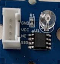
Pin Configuration
The Grove - Light Sensor uses a 4-pin Grove connector. Below is the pinout description:
| Pin | Name | Description |
|---|---|---|
| 1 | VCC | Power supply (3.3V to 5V) |
| 2 | GND | Ground |
| 3 | SIG | Analog output signal proportional to light intensity |
| 4 | NC | Not connected |
Usage Instructions
Connecting the Sensor
- Connect the Grove - Light Sensor to a compatible microcontroller or development board (e.g., Arduino UNO) using a Grove Base Shield.
- Plug the sensor into an analog input port on the Base Shield (e.g., A0).
- Ensure the microcontroller is powered and properly grounded.
Example Arduino Code
Below is an example of how to use the Grove - Light Sensor with an Arduino UNO to read and display light intensity:
// Include necessary libraries (if any Grove-specific libraries are used)
// Define the analog pin connected to the sensor
const int lightSensorPin = A0;

void setup() {
  Serial.begin(9600); // Initialize serial communication at 9600 baud
  pinMode(lightSensorPin, INPUT); // Set the sensor pin as input
}

void loop() {
  int sensorValue = analogRead(lightSensorPin); // Read the analog value
  float voltage = sensorValue * (5.0 / 1023.0); // Convert to voltage
  Serial.print("Light Intensity (Voltage): ");
  Serial.println(voltage); // Print the voltage to the Serial Monitor

  delay(500); // Wait for 500ms before the next reading
}
Important Considerations
- Power Supply: Ensure the sensor is powered within its operating voltage range (3.3V to 5V).
- Analog Signal: The output signal is analog, so it must be connected to an analog input pin on the microcontroller.
- Calibration: For precise measurements, you may need to calibrate the sensor based on your specific application and environment.
- Placement: Avoid placing the sensor in direct sunlight for extended periods, as it may affect accuracy or cause damage.
Troubleshooting and FAQs
Common Issues and Solutions
No Output Signal
- Cause: Incorrect wiring or loose connections.
- Solution: Verify that the sensor is properly connected to the microcontroller and that the power supply is within the specified range.
Inconsistent Readings
- Cause: Electrical noise or unstable power supply.
- Solution: Use a decoupling capacitor (e.g., 0.1µF) between VCC and GND to stabilize the power supply.
Low Sensitivity
- Cause: Sensor placement in a low-light environment.
- Solution: Ensure the sensor is exposed to sufficient ambient light for accurate readings.
High Readings in Darkness
- Cause: Ambient electrical interference.
- Solution: Shield the sensor from nearby electronic devices or sources of interference.
FAQs
Q1: Can the sensor detect infrared light?
A1: No, the Grove - Light Sensor is designed to detect visible light and may not respond accurately to infrared light.
Q2: Can I use this sensor with a Raspberry Pi?
A2: Yes, you can use the sensor with a Raspberry Pi by connecting it to an analog-to-digital converter (ADC), as the Raspberry Pi does not have built-in analog input pins.
Q3: How do I extend the sensor's cable length?
A3: You can use Grove-compatible extension cables, but ensure the total length does not introduce significant signal degradation.
Q4: Is the sensor waterproof?
A4: No, the sensor is not waterproof. Avoid exposing it to moisture or water.
By following this documentation, you can effectively integrate and utilize the Grove - Light Sensor in your projects.