How to Use 42 57 Stepper Motor Driver Controller: Examples, Pinouts, and Specs
Introduction
The BANRIA 42 57 Stepper Motor Driver Controller (Part ID: B0B1HNS9L2) is a versatile device designed to control the position, speed, and torque of stepper motors by sending precise electrical pulses. This component is essential for applications requiring accurate motor control, such as 3D printers, CNC machines, and robotic arms.
Explore Projects Built with 42 57 Stepper Motor Driver Controller


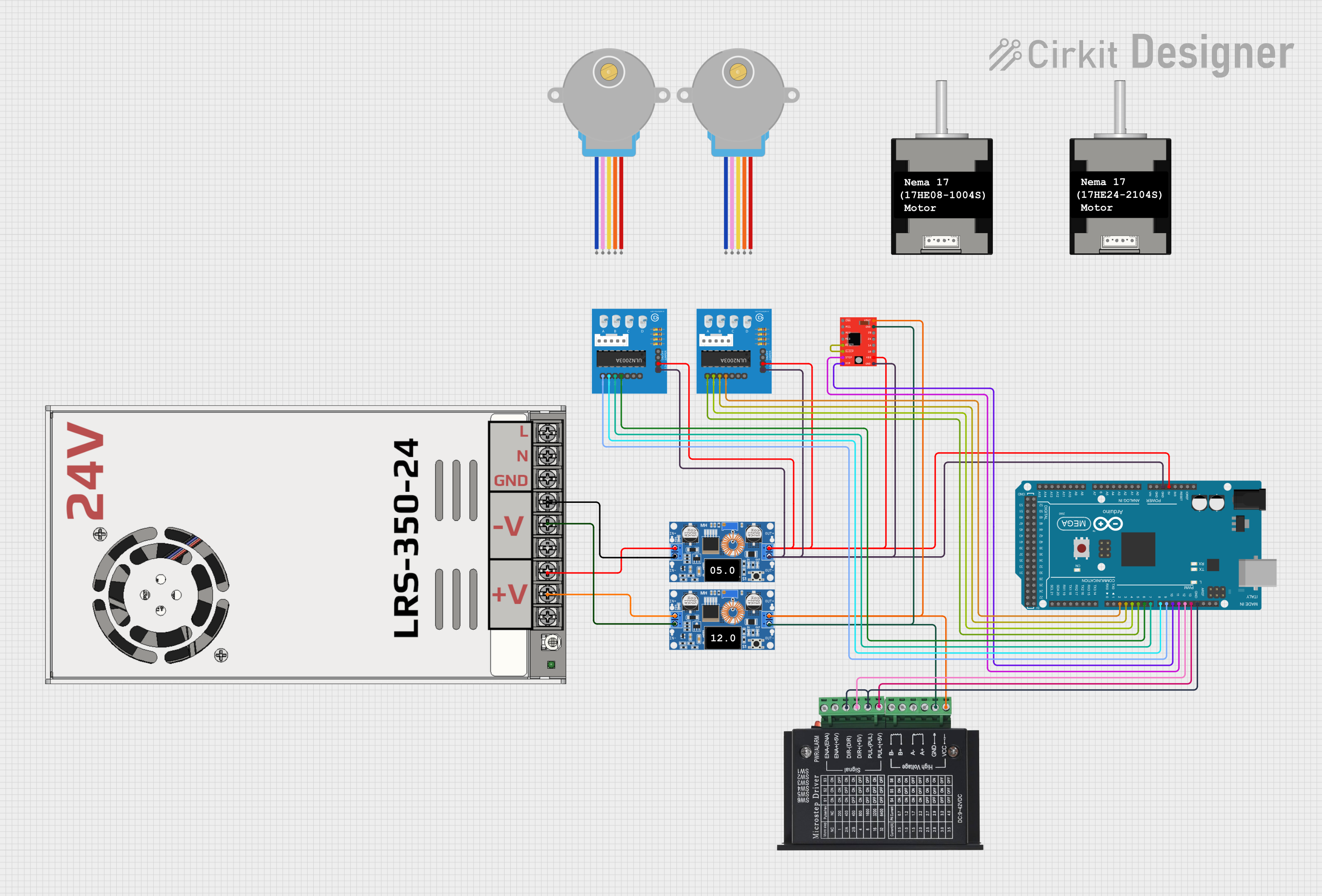
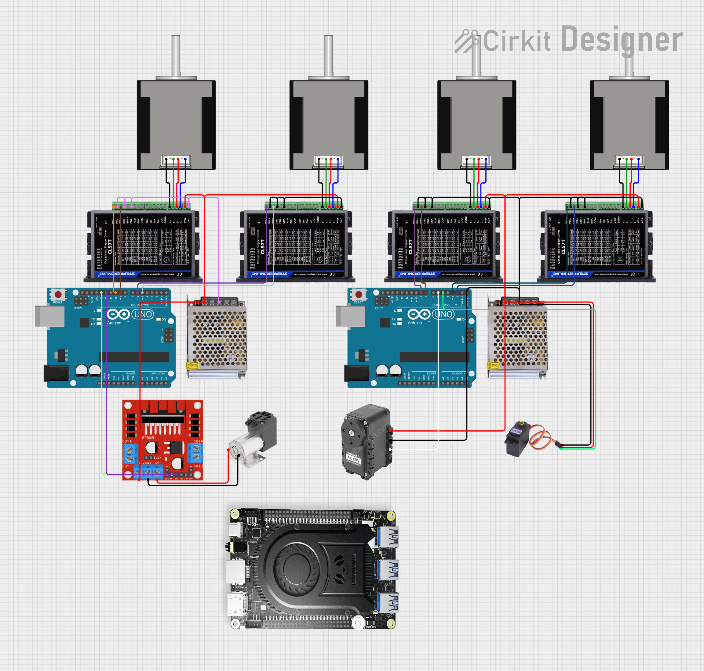
Explore Projects Built with 42 57 Stepper Motor Driver Controller
Technical Specifications
Key Technical Details
| Parameter | Value |
|---|---|
| Input Voltage | 12V - 36V DC |
| Output Current | 0.5A - 4.2A |
| Microstepping | 1, 1/2, 1/4, 1/8, 1/16, 1/32 |
| Control Signal | Pulse/Direction |
| Operating Temperature | -10°C to +45°C |
| Dimensions | 96mm x 56mm x 33mm |
Pin Configuration and Descriptions
| Pin No. | Pin Name | Description |
|---|---|---|
| 1 | PUL+ | Pulse signal input (+) |
| 2 | PUL- | Pulse signal input (-) |
| 3 | DIR+ | Direction signal input (+) |
| 4 | DIR- | Direction signal input (-) |
| 5 | ENA+ | Enable signal input (+) |
| 6 | ENA- | Enable signal input (-) |
| 7 | A+ | Motor phase A+ |
| 8 | A- | Motor phase A- |
| 9 | B+ | Motor phase B+ |
| 10 | B- | Motor phase B- |
| 11 | VCC | Power supply input (12V - 36V DC) |
| 12 | GND | Ground |
Usage Instructions
How to Use the Component in a Circuit
Power Supply Connection:
- Connect the VCC pin to a 12V - 36V DC power supply.
- Connect the GND pin to the ground of the power supply.
Motor Connection:
- Connect the stepper motor's phase A wires to the A+ and A- pins.
- Connect the stepper motor's phase B wires to the B+ and B- pins.
Control Signal Connection:
- Connect the PUL+ and PUL- pins to the pulse signal source.
- Connect the DIR+ and DIR- pins to the direction signal source.
- Optionally, connect the ENA+ and ENA- pins to an enable signal source.
Important Considerations and Best Practices
- Ensure the power supply voltage is within the specified range (12V - 36V DC).
- Use appropriate heat dissipation methods, such as heat sinks or cooling fans, to prevent overheating.
- Verify the wiring connections before powering on the device to avoid damage.
- Adjust the microstepping settings according to the desired resolution and smoothness of motor movement.
Troubleshooting and FAQs
Common Issues and Solutions
Motor Not Moving:
- Solution: Check the power supply connection and ensure it is within the specified voltage range. Verify the control signal connections (PUL+, PUL-, DIR+, DIR-).
Motor Moving in the Wrong Direction:
- Solution: Reverse the connections of the DIR+ and DIR- pins.
Overheating:
- Solution: Ensure proper heat dissipation using heat sinks or cooling fans. Reduce the output current if necessary.
Inconsistent Motor Movement:
- Solution: Check the microstepping settings and ensure they are configured correctly. Verify the pulse signal source for consistency.
FAQs
Q1: Can I use this driver with an Arduino UNO?
- A1: Yes, the BANRIA 42 57 Stepper Motor Driver Controller can be used with an Arduino UNO. Below is an example code to control the stepper motor using the Arduino UNO.
// Arduino UNO - Stepper Motor Control Example

const int pulsePin = 2; // Pulse signal pin
const int dirPin = 3;   // Direction signal pin
const int enaPin = 4;   // Enable signal pin

void setup() {
  pinMode(pulsePin, OUTPUT);
  pinMode(dirPin, OUTPUT);
  pinMode(enaPin, OUTPUT);

  digitalWrite(enaPin, LOW); // Enable the driver
  digitalWrite(dirPin, HIGH); // Set direction
}

void loop() {
  digitalWrite(pulsePin, HIGH);
  delayMicroseconds(500); // Adjust delay for speed control
  digitalWrite(pulsePin, LOW);
  delayMicroseconds(500); // Adjust delay for speed control
}
Q2: What is microstepping, and how do I configure it?
- A2: Microstepping is a technique used to increase the resolution and smoothness of stepper motor movement. The BANRIA 42 57 Stepper Motor Driver Controller supports various microstepping settings (1, 1/2, 1/4, 1/8, 1/16, 1/32). Refer to the manufacturer's datasheet for detailed instructions on configuring microstepping.
Q3: How do I adjust the output current?
- A3: The output current can be adjusted using the onboard potentiometer. Refer to the manufacturer's datasheet for detailed instructions on adjusting the current.
By following this documentation, users can effectively utilize the BANRIA 42 57 Stepper Motor Driver Controller in their projects, ensuring accurate and reliable motor control.