How to Use AS5048 Magnetic Encoder Position Sensor: Examples, Pinouts, and Specs
Introduction
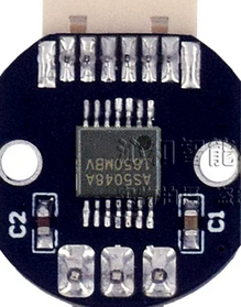
The AS5048 is a precise magnetic rotary encoder sensor that provides a full 360-degree range of angle measurement. It is designed to output the absolute position of the magnet's rotation angle via a digital interface, which can be SPI (Serial Peripheral Interface) or I2C (Inter-Integrated Circuit), depending on the variant of the sensor. This sensor is commonly used in robotics, motor control, and other applications where accurate angular measurements are critical.
Explore Projects Built with AS5048 Magnetic Encoder Position Sensor
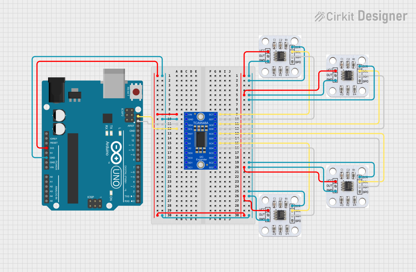
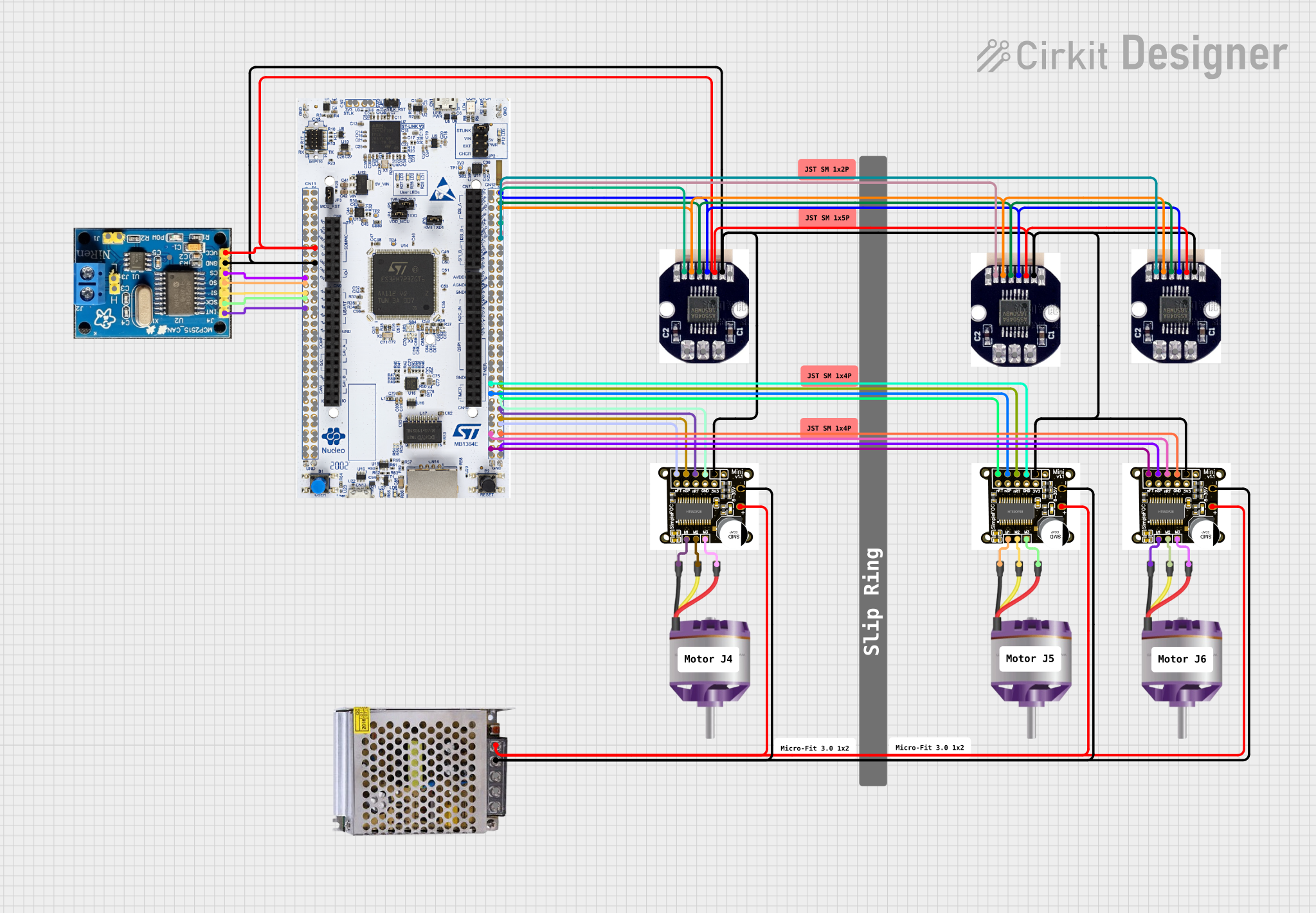

Explore Projects Built with AS5048 Magnetic Encoder Position Sensor
Technical Specifications
Key Technical Details
- Resolution: 14-bit (16384 positions per revolution)
- Interface Options: SPI or I2C
- Supply Voltage: 3.3V to 5V
- Maximum Rotation Speed: 14,000 rpm (revolutions per minute)
- Operating Temperature Range: -40°C to +125°C
Pin Configuration and Descriptions
| Pin Number | Name | Description |
|---|---|---|
| 1 | VDD | Power supply (3.3V to 5V) |
| 2 | GND | Ground connection |
| 3 | SCL/CLK | Serial clock line for I2C/SPI |
| 4 | SDA/DO | Serial data line for I2C, Data output for SPI |
| 5 | NCS | Chip select for SPI (active low) |
| 6 | PWM/FSYNC | PWM output / Frame synchronization for SPI |
| 7 | A1 | Address pin 1 for I2C (LSB) |
| 8 | A2 | Address pin 2 for I2C |
Usage Instructions
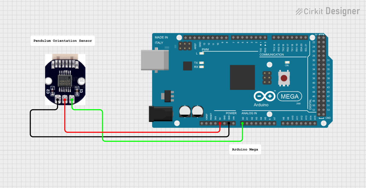
Integration into a Circuit
- Connect VDD to a 3.3V or 5V power supply.
- Connect GND to the system ground.
- For SPI communication, connect SCL/CLK to the SPI clock, SDA/DO to the SPI MISO (Master In Slave Out), and NCS to the SPI chip select on your microcontroller.
- For I2C communication, connect SCL/CLK to the I2C clock and SDA/DO to the I2C data line. Set the A1 and A2 pins to the desired address configuration by connecting them to either VDD or GND.
Important Considerations and Best Practices
- Ensure that the magnet used is within the specified range of the sensor for accurate readings.
- Avoid placing any ferromagnetic materials near the sensor as they can interfere with the magnetic field and distort readings.
- Use proper decoupling capacitors close to the power supply pins to minimize power supply noise.
Example Code for Arduino UNO
#include <SPI.h>

// Define the AS5048A SPI settings
SPISettings AS5048ASettings(1000000, MSBFIRST, SPI_MODE1);

// Define the chip select pin
const int CSPin = 10;

void setup() {
  // Set the chip select pin as an output
  pinMode(CSPin, OUTPUT);
  // Begin SPI communication
  SPI.begin();
  // Pull the chip select pin high to deselect the sensor
  digitalWrite(CSPin, HIGH);
}

void loop() {
  // Read the angle from the sensor
  unsigned int angle = readAS5048A();
  // Print the angle to the Serial Monitor
  Serial.println(angle);
  delay(1000); // Wait for 1 second
}

unsigned int readAS5048A() {
  // Variable to store the angle
  unsigned int angle = 0;
  // Pull the chip select pin low to select the sensor
  digitalWrite(CSPin, LOW);
  // Start SPI transaction with the defined settings
  SPI.beginTransaction(AS5048ASettings);
  // Send the command to read the angle
  SPI.transfer(0xFF);
  // Read the high byte of the angle
  angle = SPI.transfer(0x00);
  // Shift the high byte and read the low byte
  angle = (angle << 8) | SPI.transfer(0x00);
  // End the SPI transaction
  SPI.endTransaction();
  // Pull the chip select pin high to deselect the sensor
  digitalWrite(CSPin, HIGH);
  // Return the angle
  return angle;
}
Troubleshooting and FAQs
Common Issues
- Inaccurate Readings: Ensure that the magnet is properly aligned and there are no ferromagnetic materials nearby that could affect the sensor's readings.
- No Data on SPI/I2C: Check the connections and ensure that the correct communication protocol is being used. Also, verify that the chip select pin is being controlled correctly for SPI.
Solutions and Tips for Troubleshooting
- Power Supply Issues: Use a multimeter to check that the power supply is within the specified range and is stable.
- Signal Integrity: Use an oscilloscope to check the integrity of the SPI or I2C signals. Look for noise or distortion that could affect communication.
- Magnet Placement: Adjust the position of the magnet relative to the sensor to ensure it is within the optimal range for detection.
FAQs
Q: Can the AS5048 be used with a 5V microcontroller? A: Yes, the AS5048 can be interfaced with both 3.3V and 5V systems.
Q: How can I change the I2C address of the sensor? A: The I2C address can be changed by configuring the A1 and A2 pins to either high or low (VDD or GND).
Q: What is the maximum distance the magnet can be from the sensor? A: The optimal distance is typically a few millimeters, but it can vary based on the magnet's strength and size. Refer to the sensor's datasheet for specific recommendations.